Willkommen zur 3MS Dokumentations
"3MS" ist eine Abkürzung für "MMMS", was für Modular Multi Material System steht
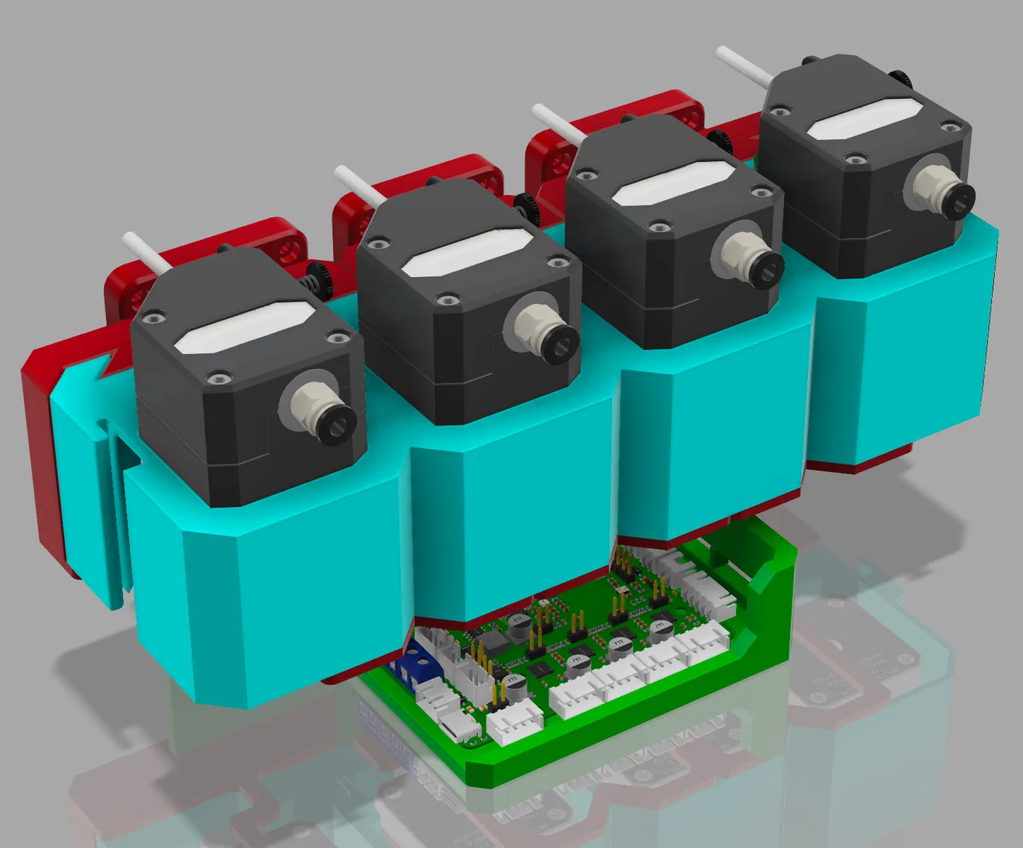

Das 3MS ist ein simpler, kompakter, modularer, verlässlicher und den Geldbeutel schonender, automatisierter Filamentwechsler.
Warum gerade das 3MS?
Warum sollte ich das 3MS verwenden, wo es doch viele andere automatisierte Filamentwechsler gibt?
Hier sind ein paar Argumente dafür:
- Einfaches Design: Minimale mechanische Komplexität für mehr Verlässlichkeit
- Geringe Kosten: Ein 3MS mit 4 Filament-Modulen kann für ~150$ USD gebaut werden
- Einfache Beschaffung: Alle Teile für das 3MS können auf Amazon erworben werden
- Verständliche Dokumentation: "Schritt-für-Schritt"-Anleitungen helfen beim reibungslosen Einrichten und Verwenden
- Skalierbar: Leicht für beliebig viele Filamente erweiterbar
Voraussetzungen
Um das 3MS verwenden zu können muss dein bisheriges Setup die folgenden Voraussetzungen erfüllen:
- Du verwendest die Klipper Firmware
- Du hast SSH (PuTTY) Zugriff (99,9% aller Klipper-Installationen erfüllen das, falls du es noch nicht verwendest solltest du das dringend ändern)
- Du hast einen freien USB-Port
- Der Extruder deines Druckers hat einen Anschluss um das Filament durch einen PTFE/Teflon-Schlauch einzuführen
- Du hast einen Filament-Sensor direkt vor dem Extruder deines Druckers
Empfehlungen
Es wird dringend empfohlen einen Filament-Cutter zu deinem Drucker hinzuzufügen um sich das Einstellen des Tip Formings zu sparen
Loslegen
Um mit dem 3MS loszulegen schau dir die Master Instructions an.
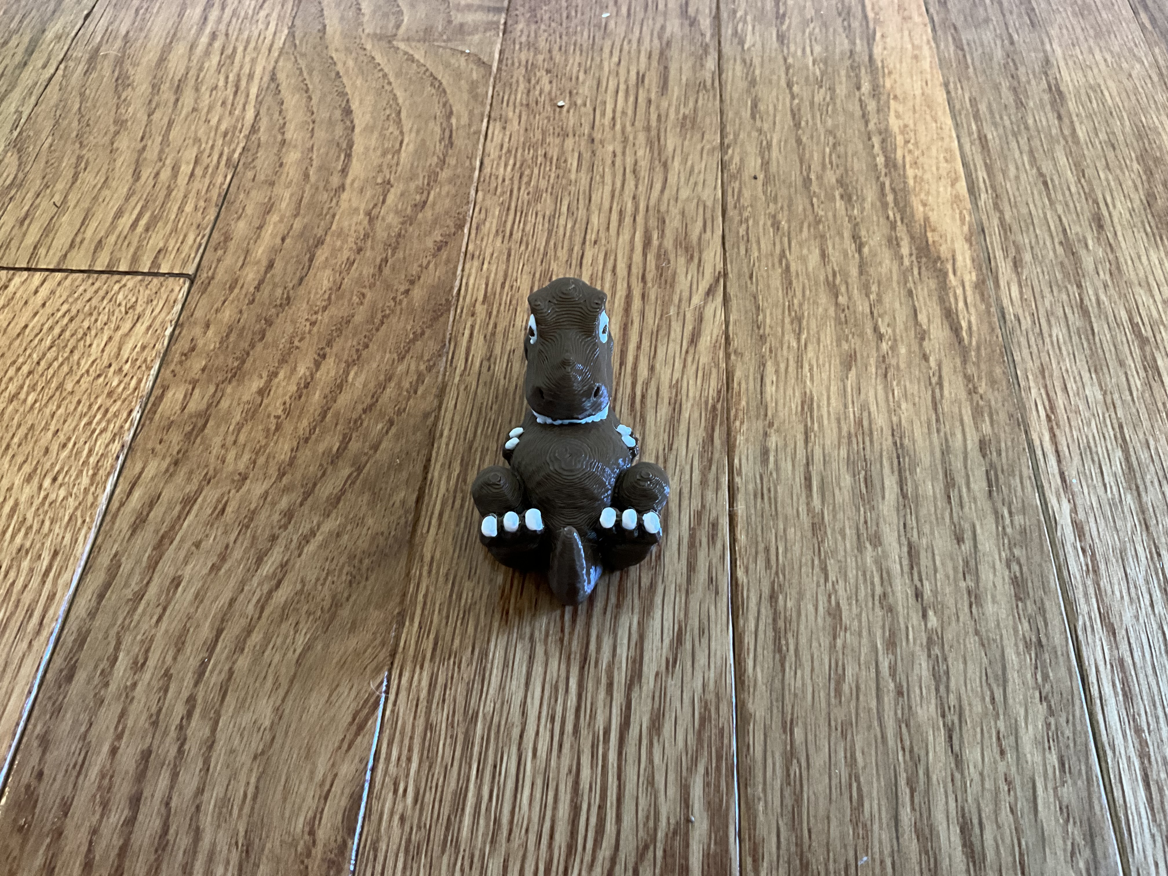
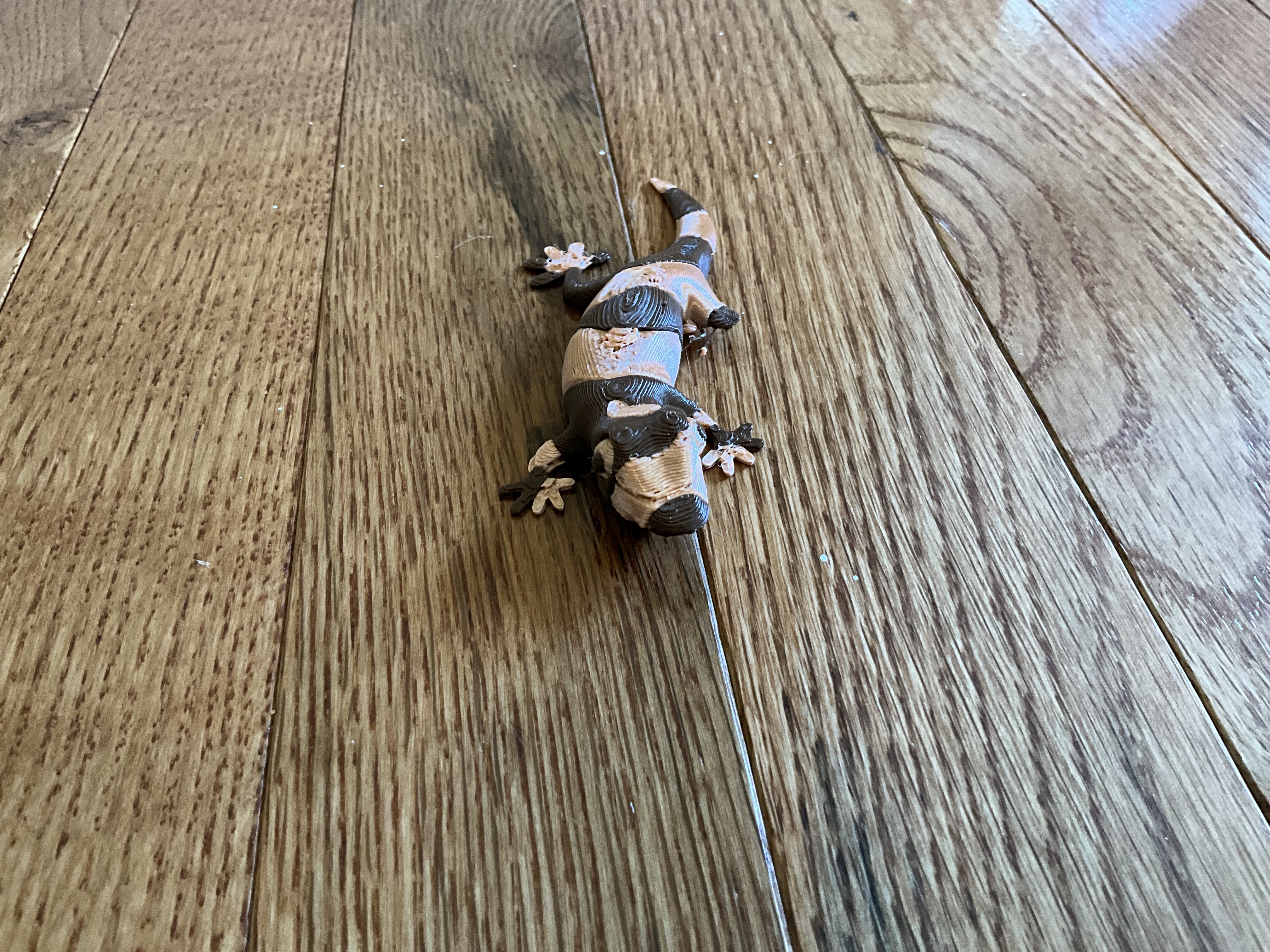
Druckergebnisse
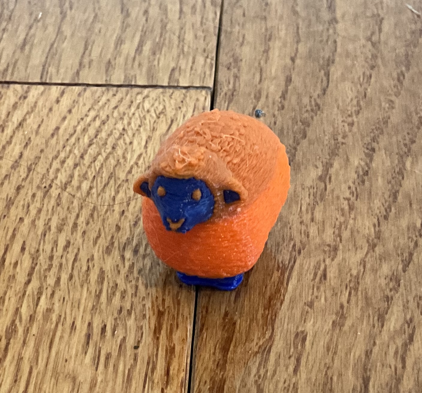
Model: "Sheep" von Cipis
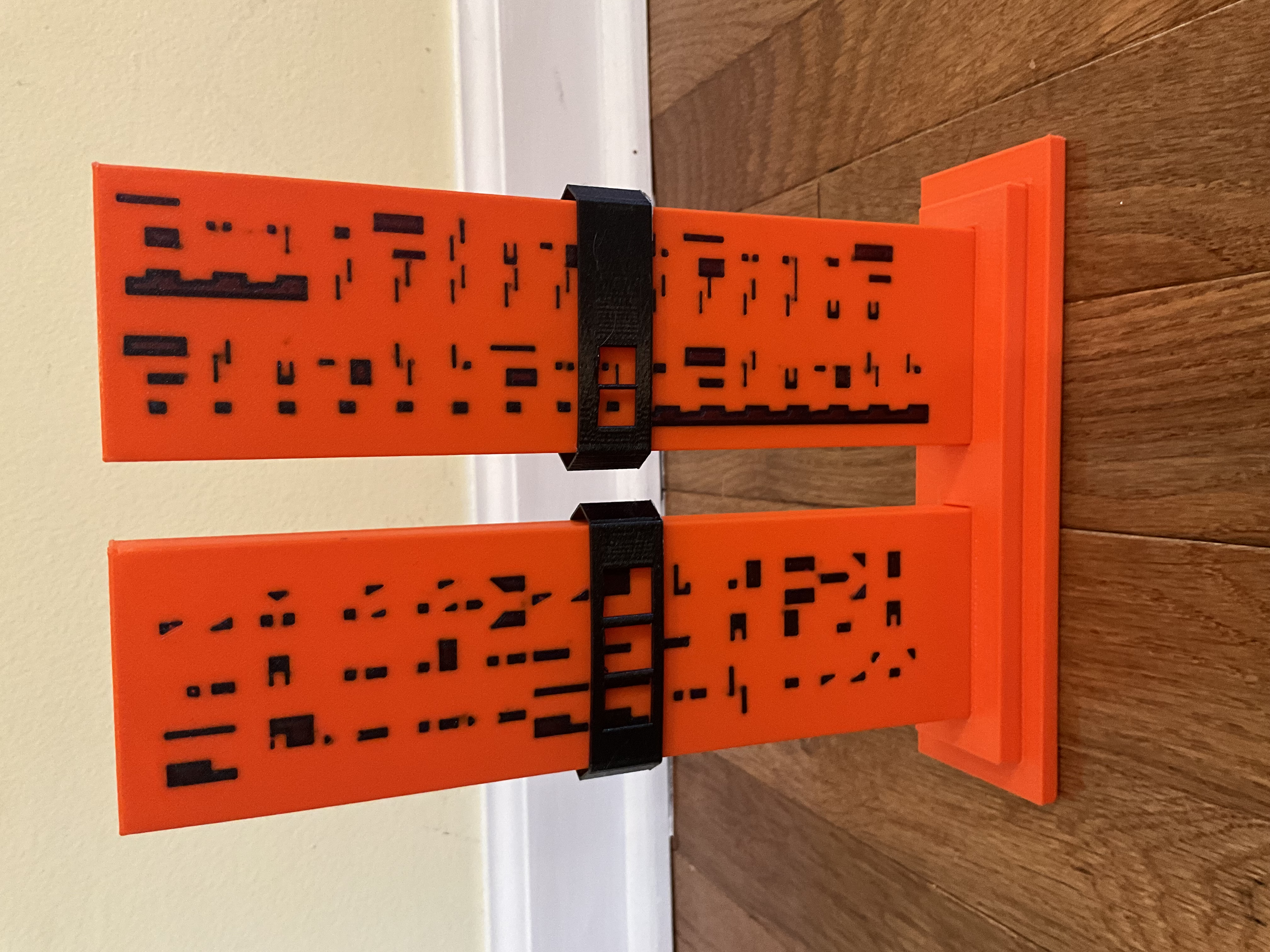
Model: Voron Cube (gebundlet mit dem OrcaSlicer), von mir angemalt im OrcaSlicer
West3D Video Serie
Danke an Allen Rowand von West3D für diese andauernde Serie über das 3MS.
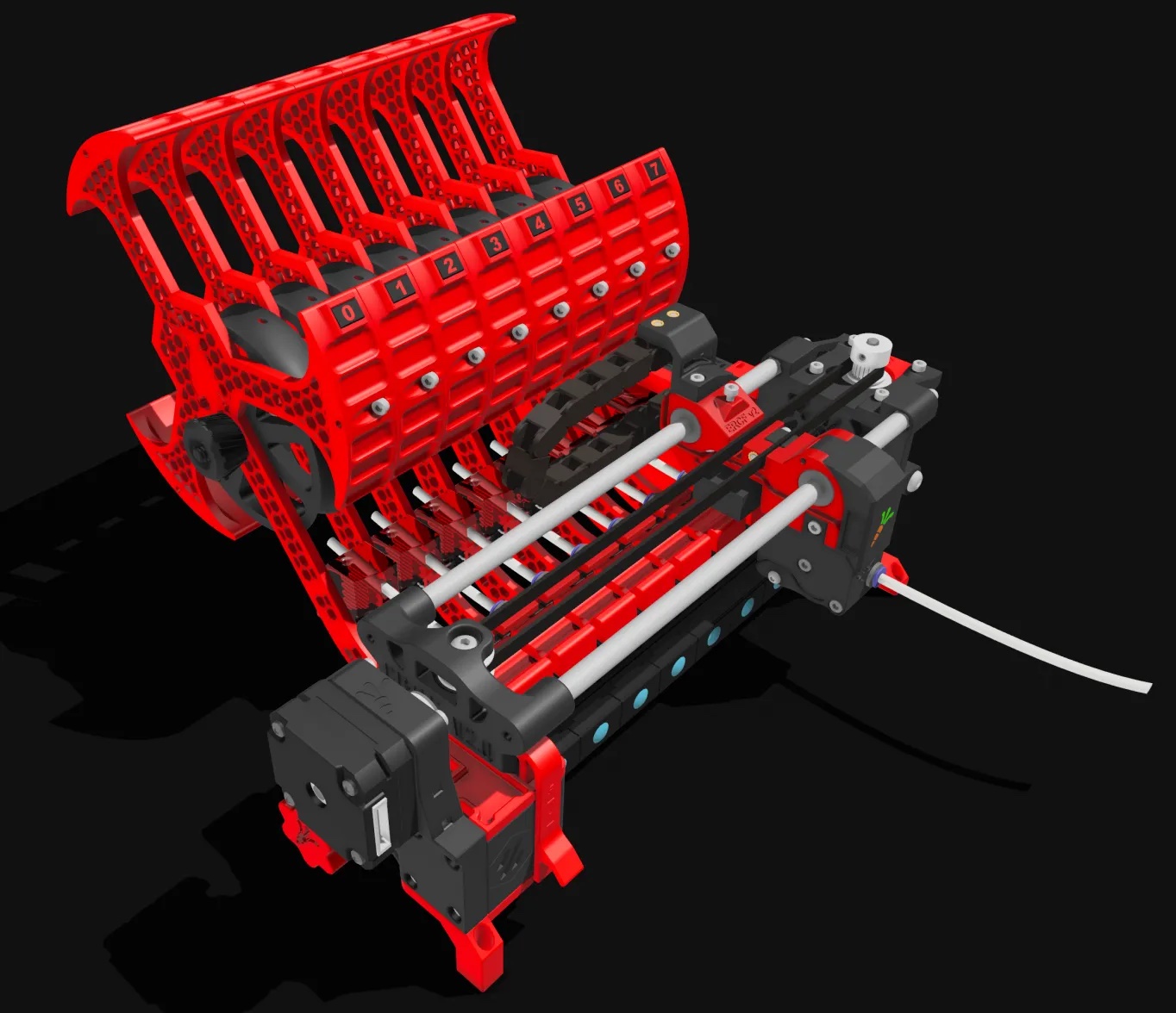
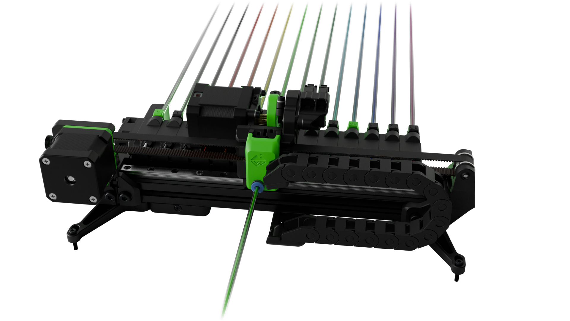
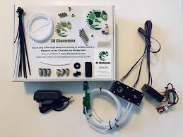
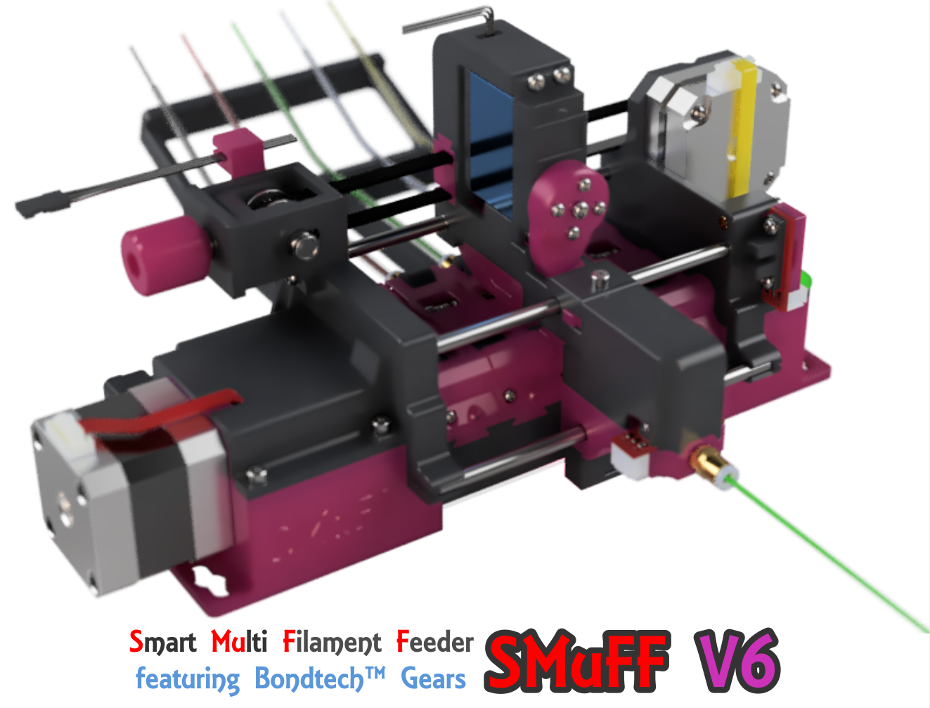
Vergleich verschiedener, automatisierter Filamentwechsler
Du bist dir unsicher ob du das 3MS verwenden willst? Schau dir doch diesen Vergleich verschiedener, verbreiteter Multimaterial-Systeme an.
-
3MS Modular Multimaterial System für Klipper 3D-Drucker
Pro:
Einfaches Design
Verlässlichkeit
Dokumentation
Modulares Design
Aktive Community
Preis (~$150)
Kontra:
Kompatibilität (erfordert Klipper)
-
Box Turtle MMU Automatisierter Filamentwechsler
Pro:
Verlässlichkeit
Aktive Community
Dokumentation
Kontra:
Kompatibilität (erfordert Klipper)
Komplexität
Preis ($300)
-
ERCF v2 Ein erweiterbares MMU für Klipper-basierte 3D-Drucker
Pro:
Verlässlichkeit
Modulares Design
Aktive Community
Dokumentation
Kontra:
Kompatibilität (erfordert Klipper)
Komplexität
-
TradRack von Annex Engineering
Pro:
Verlässlichkeit
Modulares Design
Aktive Community
Dokumentation
Kontra:
Kompatibilität (erfordert Klipper)
Komplexität
-
3DChameleon MK4 Automatic Color Changer
Pro:
Kompatibilität
keine Custom Firmware
Preis ($200)
Kontra:
Verlässlichkeit
Dokumentation
-
SMuFF "Smart Multi Filament Feeder"
Pro:
Verlässlichkeit
Modulares Design
Dokumentation
Kontra:
Komplexität
-
Prusa MMU3 Multi Material Upgrade
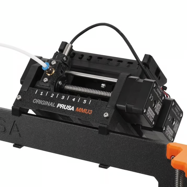
Pro:
Verlässlichkeit
Support
Dokumentation
Kontra:
Kompatibilität
Preis ($300)
-
CoPrint KCM Multi-Color Upgrade Kit für Klipper 3D-Drucker
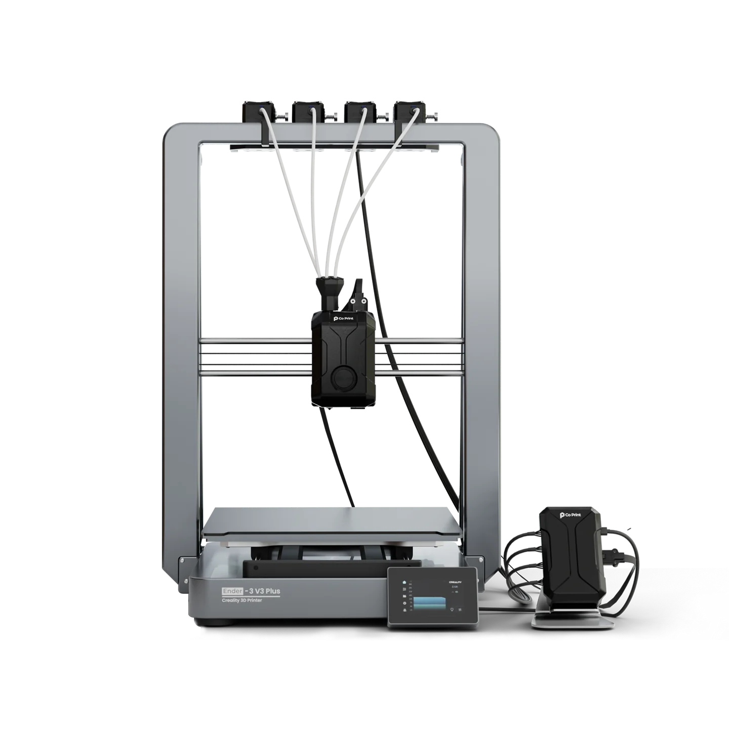
Pro:
Einfaches Design
Modulares Design
Dokumentation
Kontra:
Komplexität (erfordert ChromaHead)
Preis (~$300)
Tips / FAQ
Which board should I use?
The recommended board for the 3MS is the SKR Pico due to its compact size, reliability, and cost-effectiveness.
What sensors do I need?
To use the 3MS, you need a sensor between the exit of the Y-splitter and your printer's extruder. If it's closer to the Y-splitter, it's considered a shared gate sensor while if it's closer to the extruder it's called an extruder entry sensor.
Do I need a filament cutter?
Using a filament cutter is recommended as it takes a lot of the guesswork out of tuning tip forming. A quick Google search of "filament cutter for [MY PRINTER]" is usually good to find a filament cutter for your printer.
You can find user-submitted tip cutting/forming configurations here.
If there isn't a filament cutter published for your printer, you have two options:
-
Design your own
-
Tune tip forming
The latter option may seem easier at first, but tip forming isn't as straightforward as you might think.
Here are a few general tips:
- If your tips come out stringy, use more cooling moves and a lower temperature. Also, skinnydip string reduction can help here.
- If your tips come out with a larger tip, use less cooling moves and a higher temperature.
- Use Happy Hare's
_MMU_FORM_TIPmacro to help tune your tips.
Why isn't MMU_LOAD/MMU_UNLOAD loading/unload the filament enough?
Run the below command in Mainsail/Fluidd:
The output will show exactly what Happy Hare does on load and unload. You can look at the referenced parameters (editable in mmu_parameters.cfg) and adjust as necessary to get your load/unload just right.
More Tips / FAQ's always welcome!
Instructions
Master Instructions
Follow this guide to assemble your 3MS. A special thank you if you purchased a kit!
Feel free to ask on the 3MS Discord any time if you need help during your build!
Chapters
Stückliste
Controller-Auswahl
Such dir zuerst das Kontrollboard aus, das du für dein 3MS verwenden willst. Du kannst aus den Folgenden wählen.
Anzahl der Filament-Einheiten
Entscheide wie viele Filament-Einheiten du willst. Jede Filament-Einheit erlaubt es dir mit einem weiteren Filament zu drucken. 2 Filament-Einheiten sind das Minimum. Du kannst Filament-Einheiten auch nach dem Aufbau hinzufügen oder entfernen, aber die Stückliste und die Config werden sich abhängig von der Anzahl an Filament-Einheiten verändern.
Kontrollboard Stückliste
Wähle die zu deinem Controller passende Stückliste aus:
Empfohlen: BTT SKR Pico
Andere Kontrollboards
Filament-Einheiten Stückliste
Pro Filament-Einheit benötigst du folgendes:
| Name | Menge | Preis | Link | Anmerkungen |
|---|---|---|---|---|
| NEMA17 Stepper Motor | 1 | $9.99 | Amazon | Du kannst auch die flacheren "pancake"-Stepper verwenden, aber hast dadurch weniger Drehmoment |
| MK8 Metal Extruder | 1 | $9.99 | Amazon | Alternativ kannst du auch diesen Dual-drive MK8 basierten Extruder verwenden |
| PTFE Schlauch | 1 | $8.99 | Amazon | Du wirst diesen Schlauch nicht für jede Filament-Einheit benötigen, weil der Schlauch in der Regel zu lang für nur eine Einheit ist |
Printed Parts & Tools
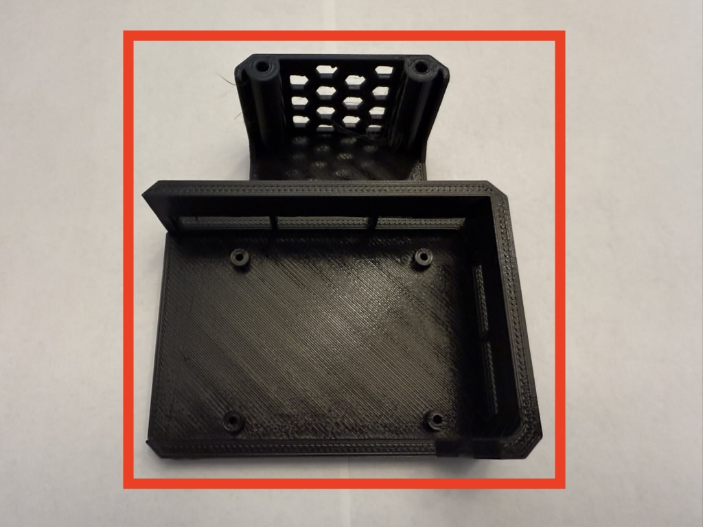
Step 1 3HOME Enclosure

-
Print out the 3HOME Official Modular Enclosure for the 3MS.
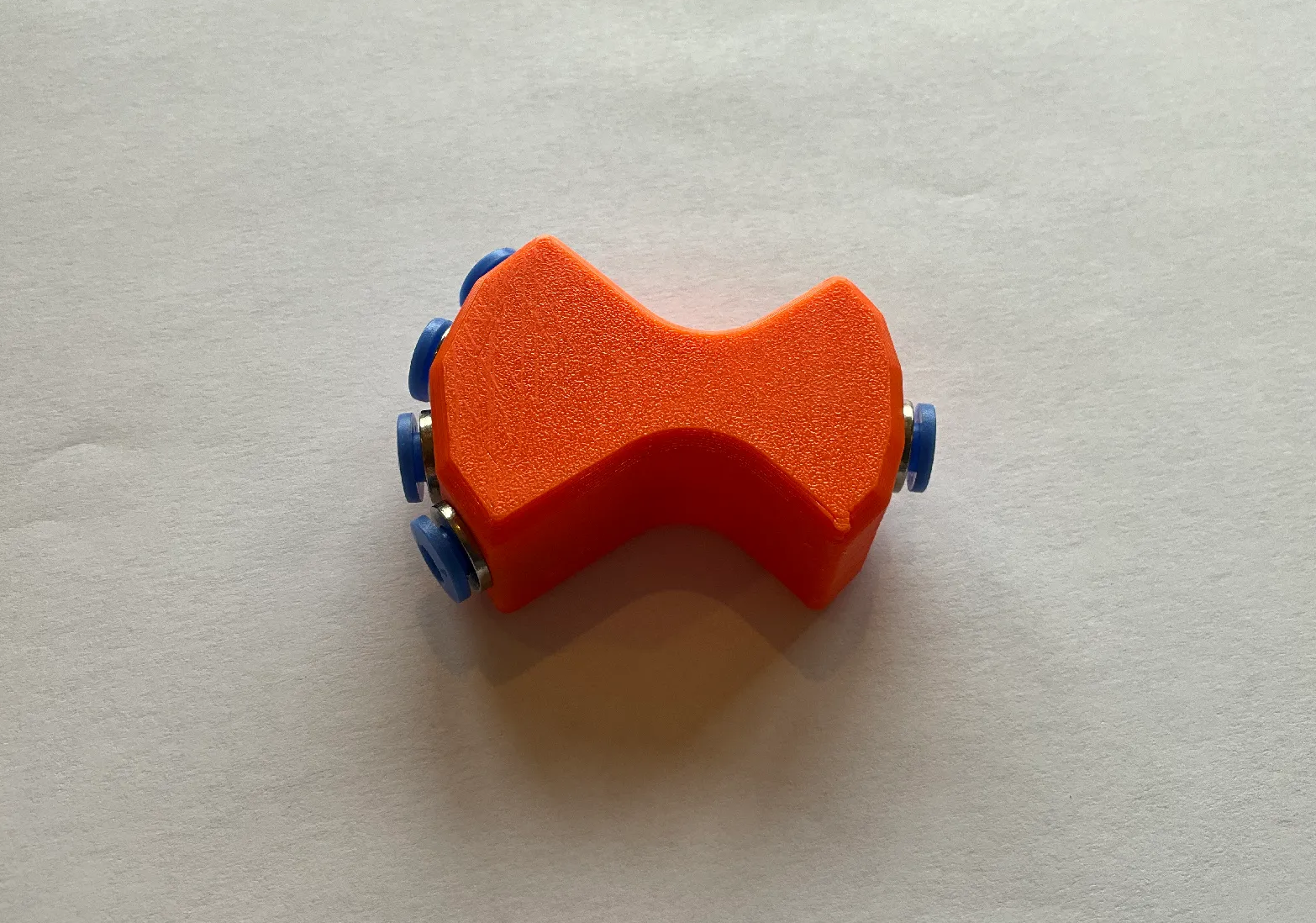
Step 2 Y-splitter
-
Print out one 4-way Y-splitter.
Alternate Splitters
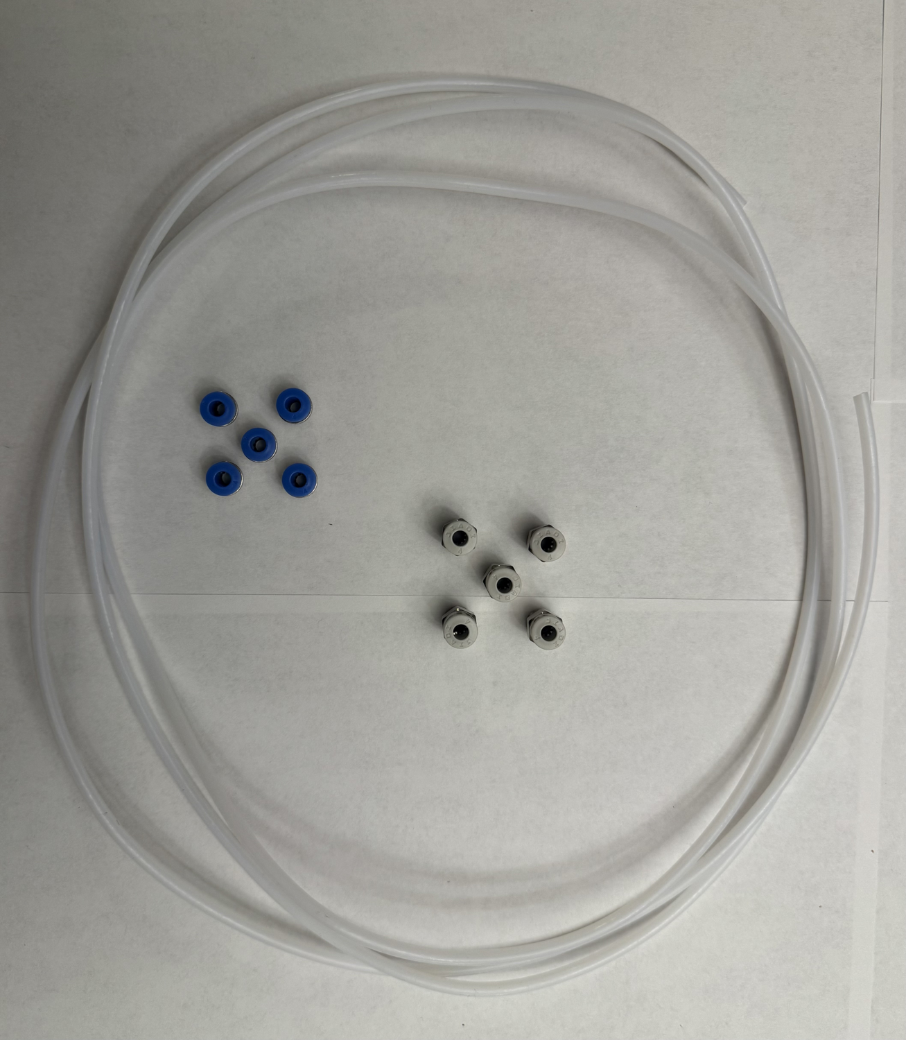
The linked Y-splitter uses five ECAS04 fittings, which are included in your 3MS kit. For your convenience, five PC4-M10 fittings are also included if you prefer to use an alternate Y-splitter design.
Step 3 Hex Keys
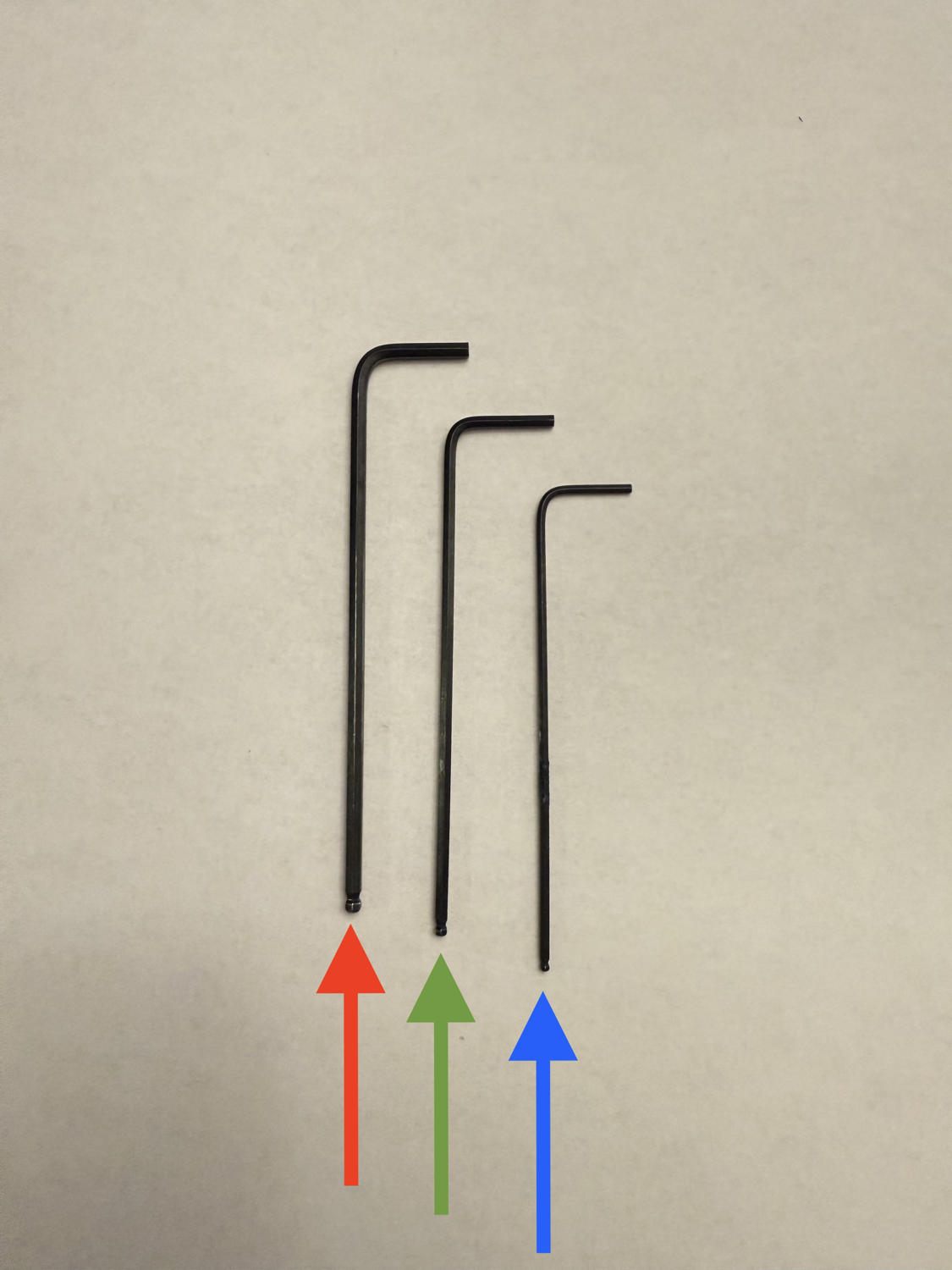
-
Ensure you have the following hex keys:
 1.5mm (included in kit but recommended to get your own)
 2mm
2mm 2.5mm (included in the kit but recommended to get your own)
Step 4 Phillips & Flat-head Screwdrivers
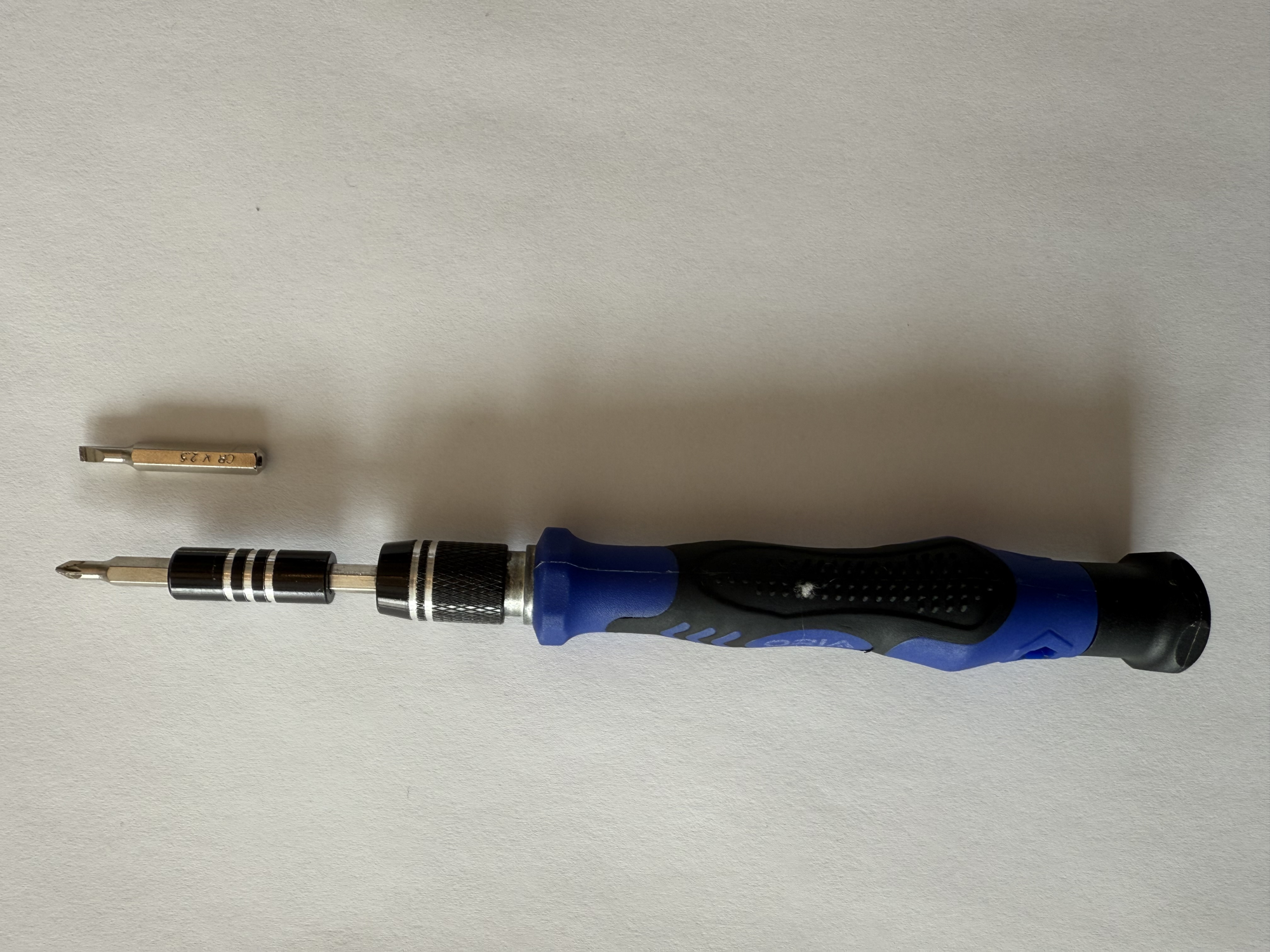
-
Ensure you have:
-
A phillips-head screwdriver (used for the screw terminals for the PSU)
-
A flat-head screwdriver (used for the screw terminals on the SKR Pico)
-
Step 5 Wire Strippers
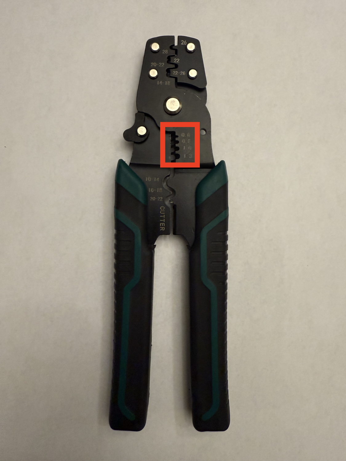
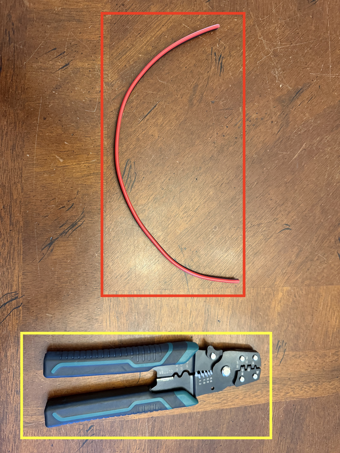
- Ensure you have wire strippers capable of stripping 24AWG wire (0.25mm2)
Step 6 Side Cutters
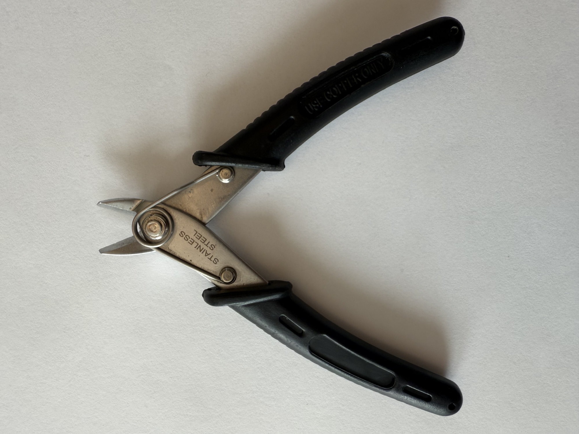
- Ensure you have side cutters (used for cutting zip ties)
Step 7 PTFE Cutters
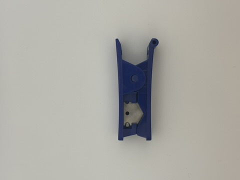
- Ensure you have a PTFE cutting tool. Alternatively, you can print a tool to cut the PTFE.
Hardware Assembly
Important
Please note that you must repeat this page four times to assemble all four extruders for your 3MS.
Step 1 Locating the Extruders Internals
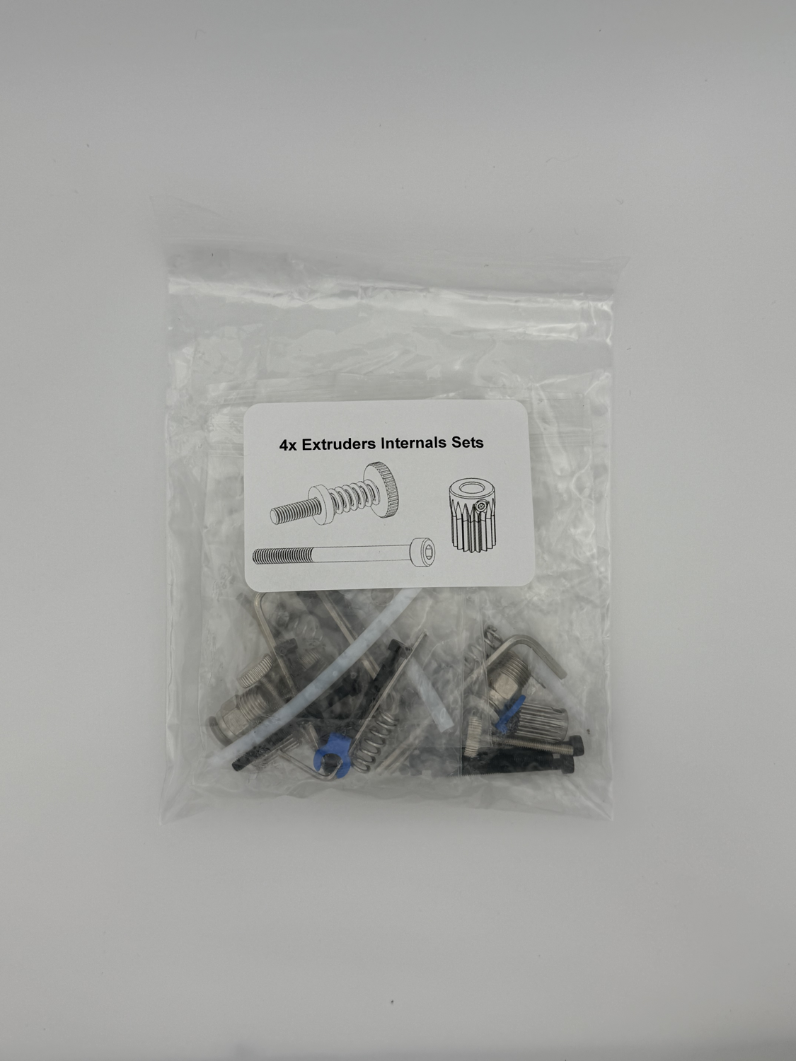
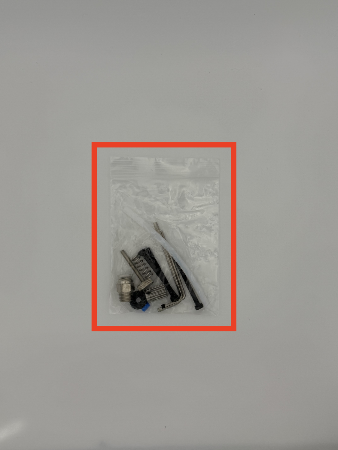
-
Begin by locating the extruders internals set in your 3MS kit.
Remove one extruder internal set from the bag.
Step 2 Preparing the Stepper Gear
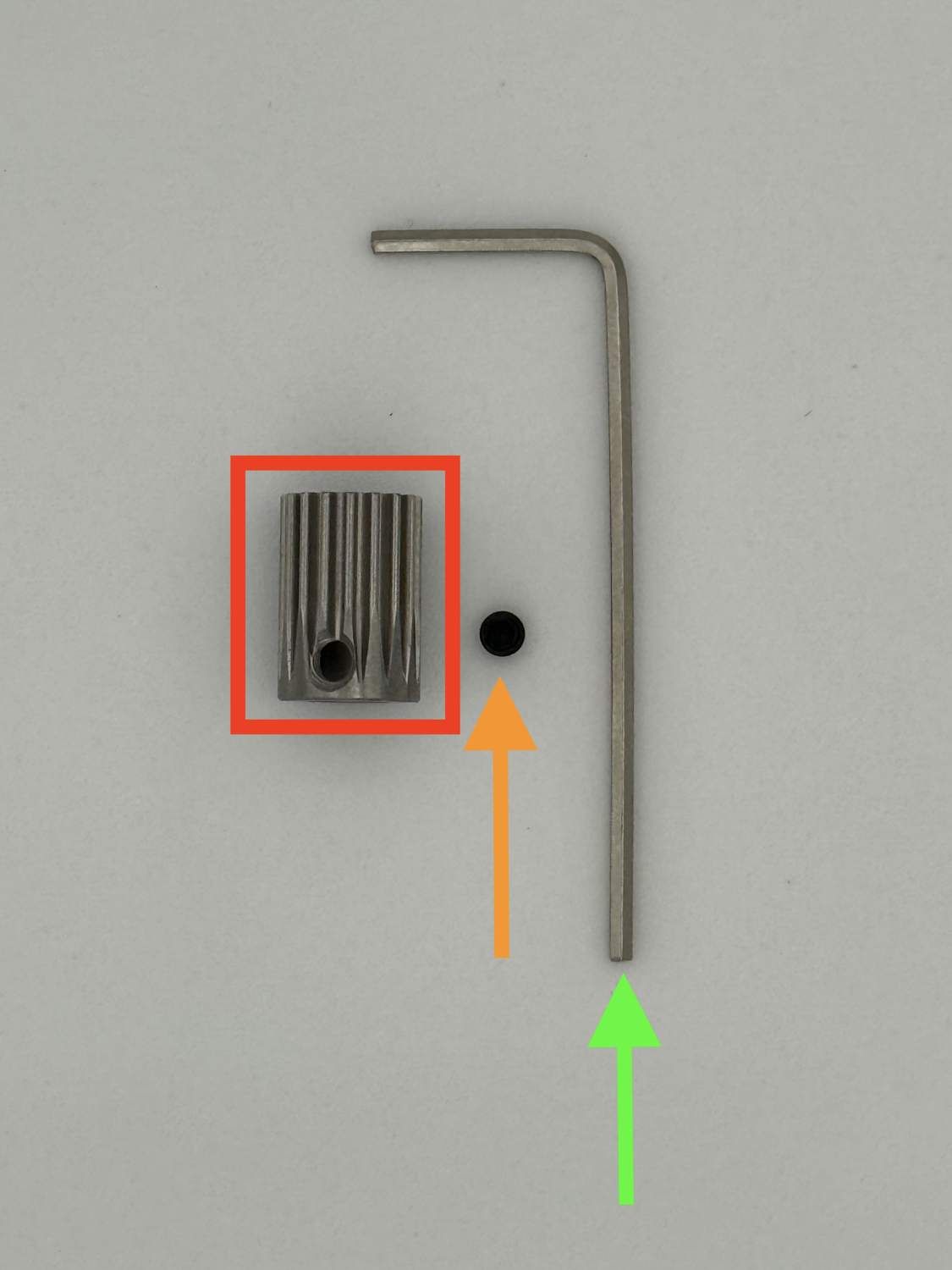
-
Prepare the following for this step:
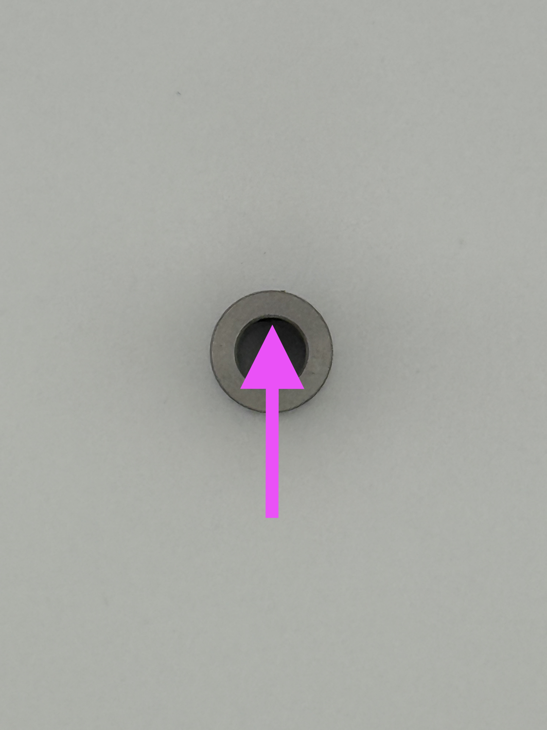
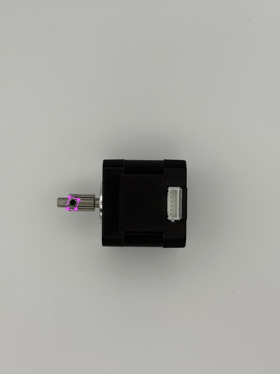
Stepper gear Stepper gear screw 1.5mm Hex key Using the 1.5mm hex key, screw the stepper gear screw into the stepper gear.
 Ensure the screw is slightly sticking into the gear.
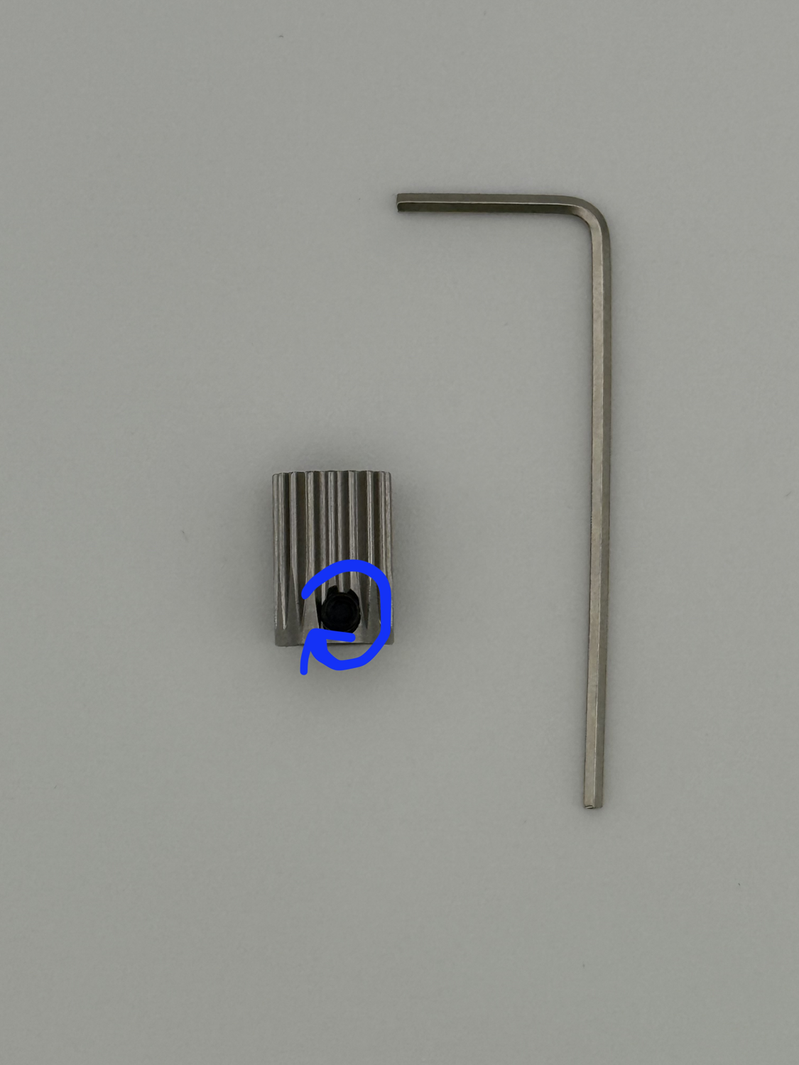
Step 3
-
Attach the stepper gear to the stepper motor.
Prepare the following for this step:
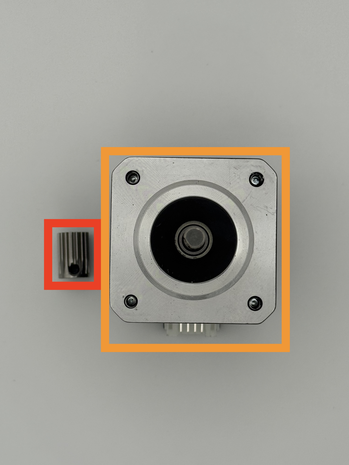
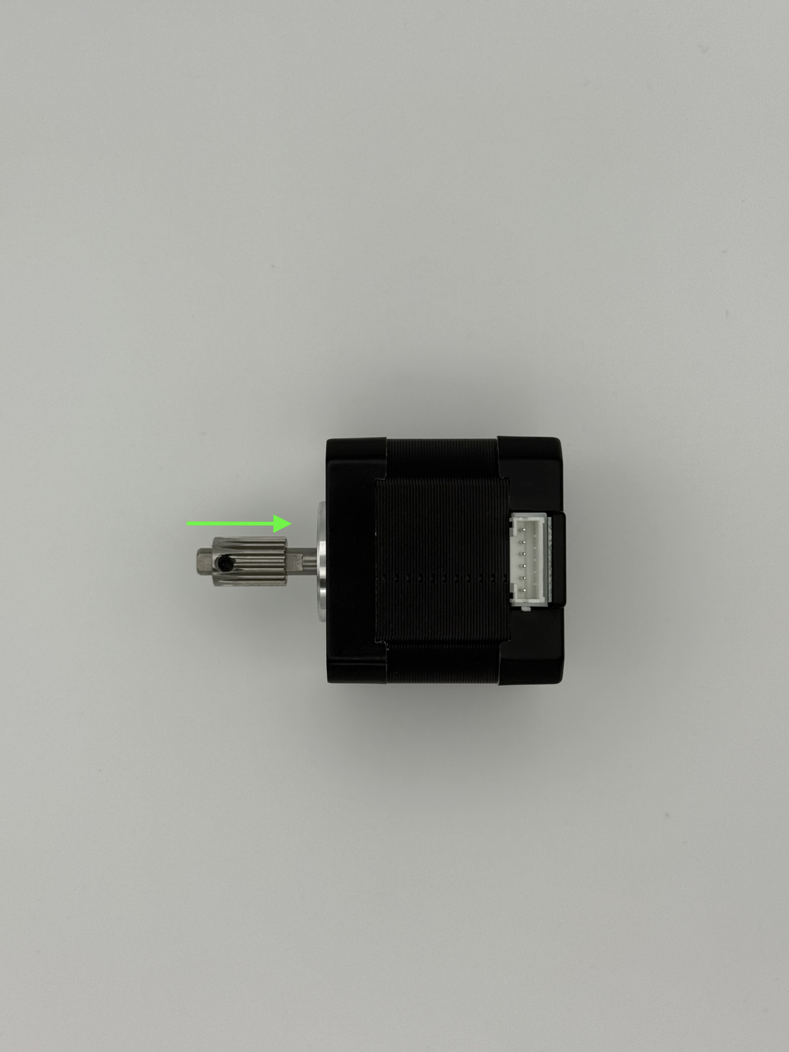
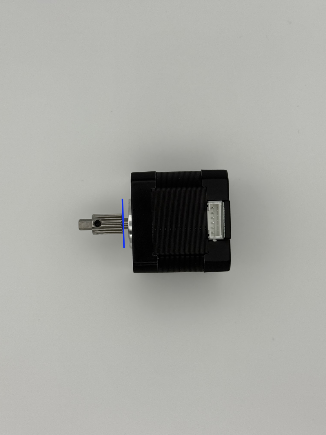
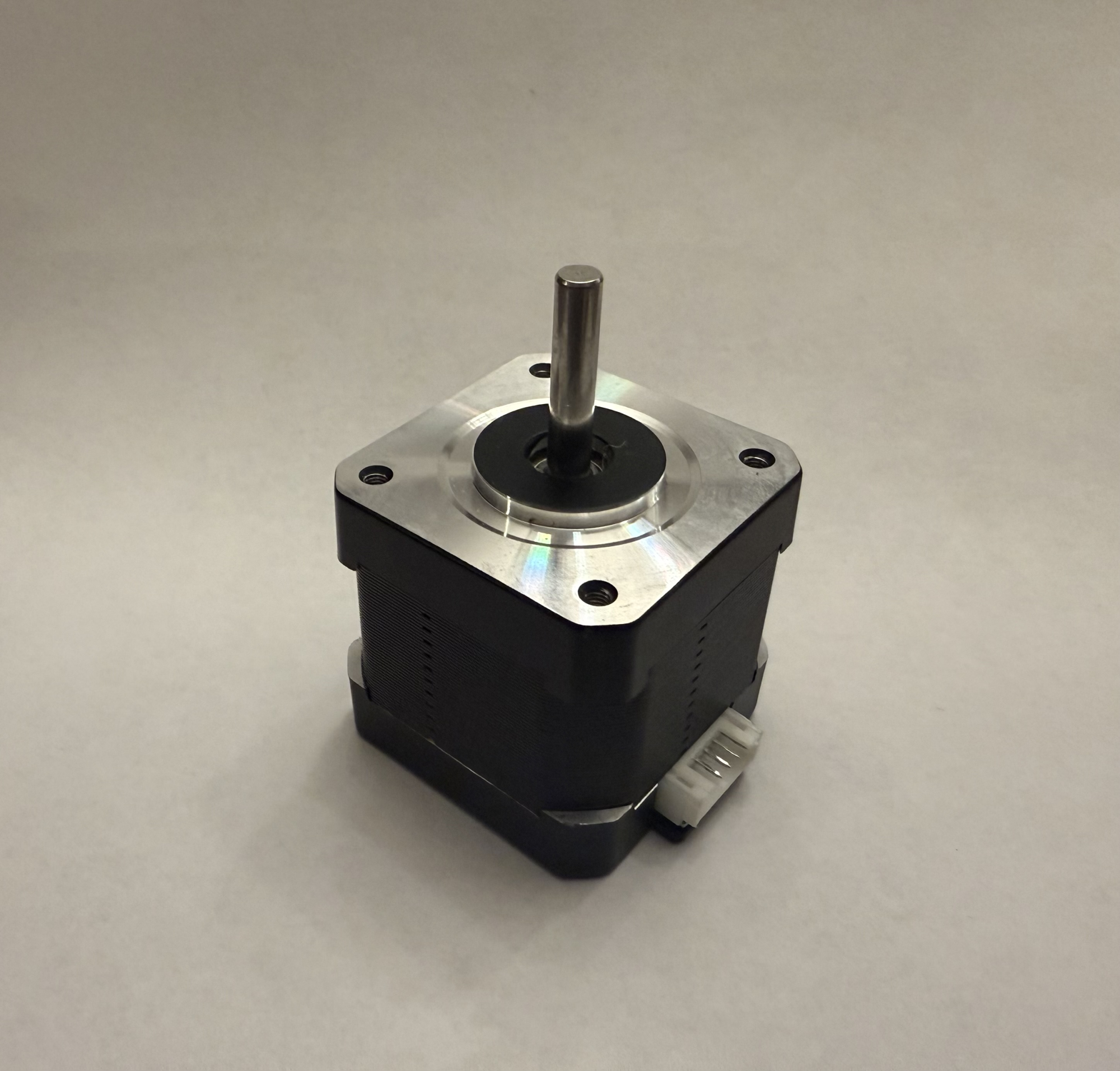
Stepper gear (prepared previously) Stepper motor Slide the stepper gear onto the stepper motor shaft. Note the orientation of the motor. Ensure the stepper gear screw is on the same side as the flat-side of the stepper motor shaft. Slide the edge of the gear to the edge of the stepper motor shaft. Tighten the stepper gear firmly.Loctite
A bit of blue loctite here can help to ensure the grub screw doesn't work its way loose over time.
Step 4 Filament Unit Parts Preparation
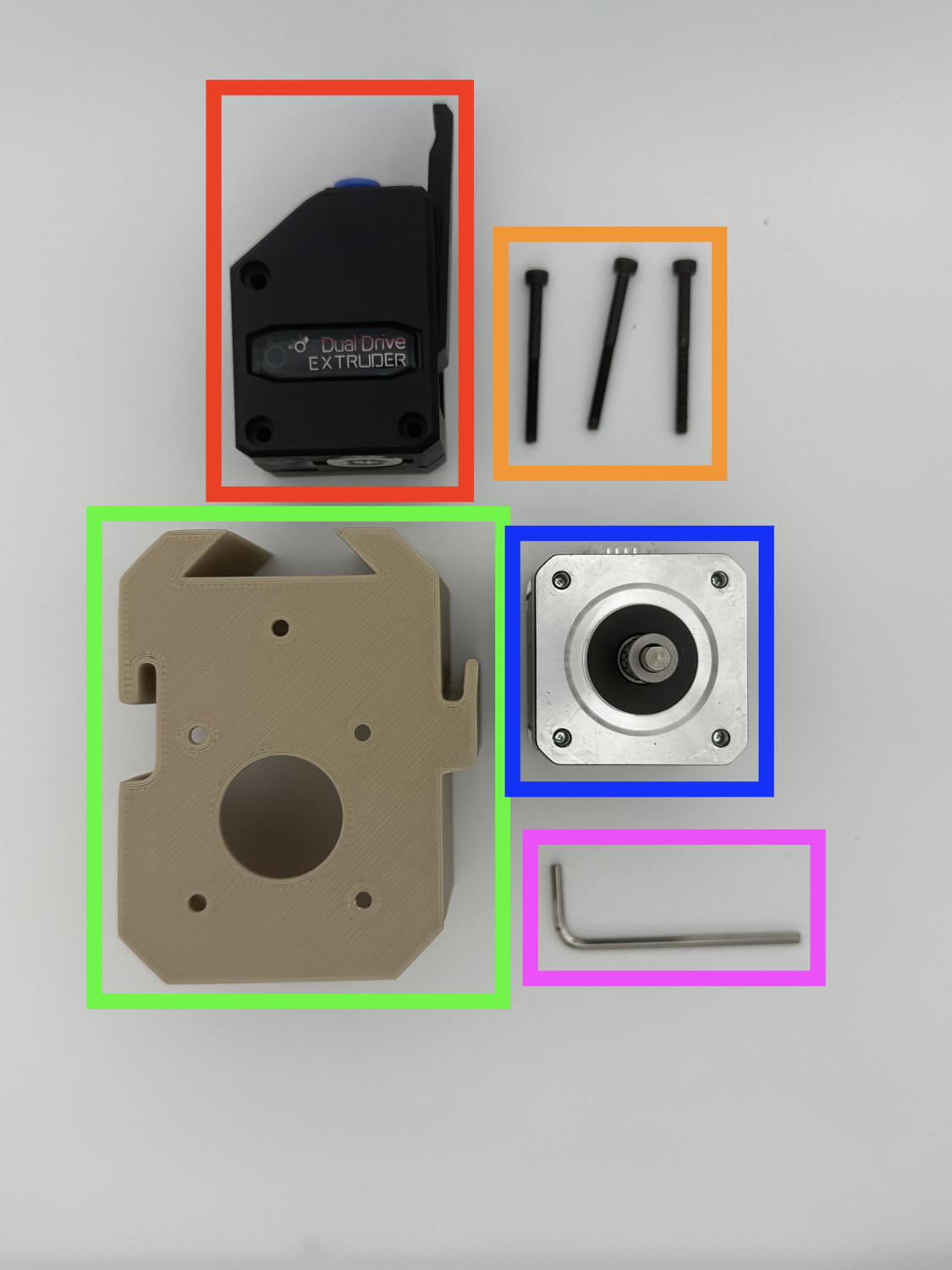
-
Prepare the following for the next steps:
Extruder 3x M3x30 SHCS (in extruders internals bag) Filament Unit for 3HOME NEMA17 Stepper motor (prepared previously) 2.5mm Hex keyLubricant
It's recommended to apply a small amount of a lubricant like SuperLube to the white extruder gear.
Step 5 Assembling the Filament Unit
-
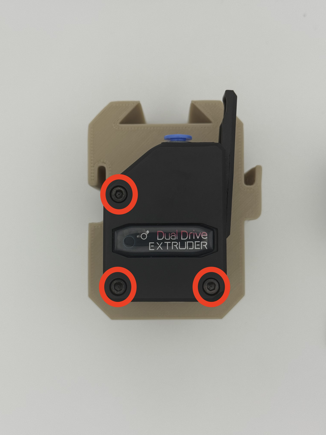
Assemble the filament unit.
Place the 3x M3x30 SHCS through the extruder into the filament unit. Note the orientation. Flip the filament unit over and place the NEMA17 stepper motor through the bottom. Note the orientation.- Even though the picture doesn't show it, it is recommended to plug the stepper cable before placing the stepper into the 3HOME.
Flip the filament unit over again and tighten the three M3 bolts.
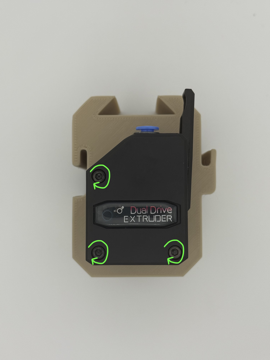
Step 6 Installing the Tensioner
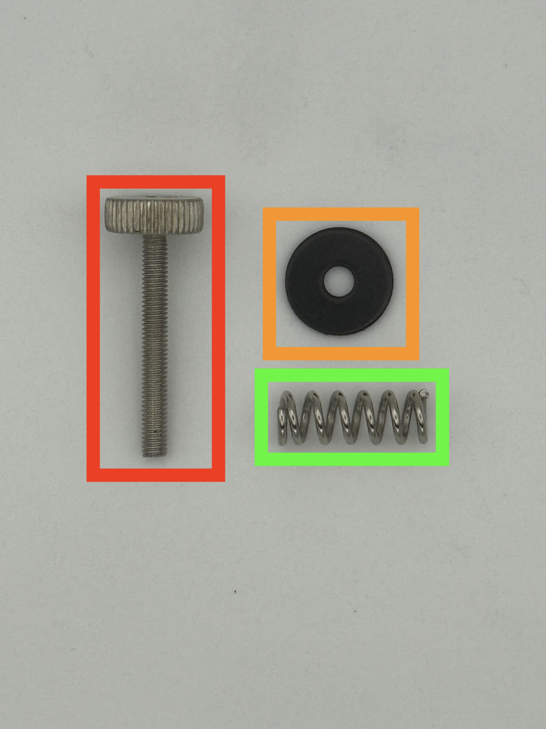
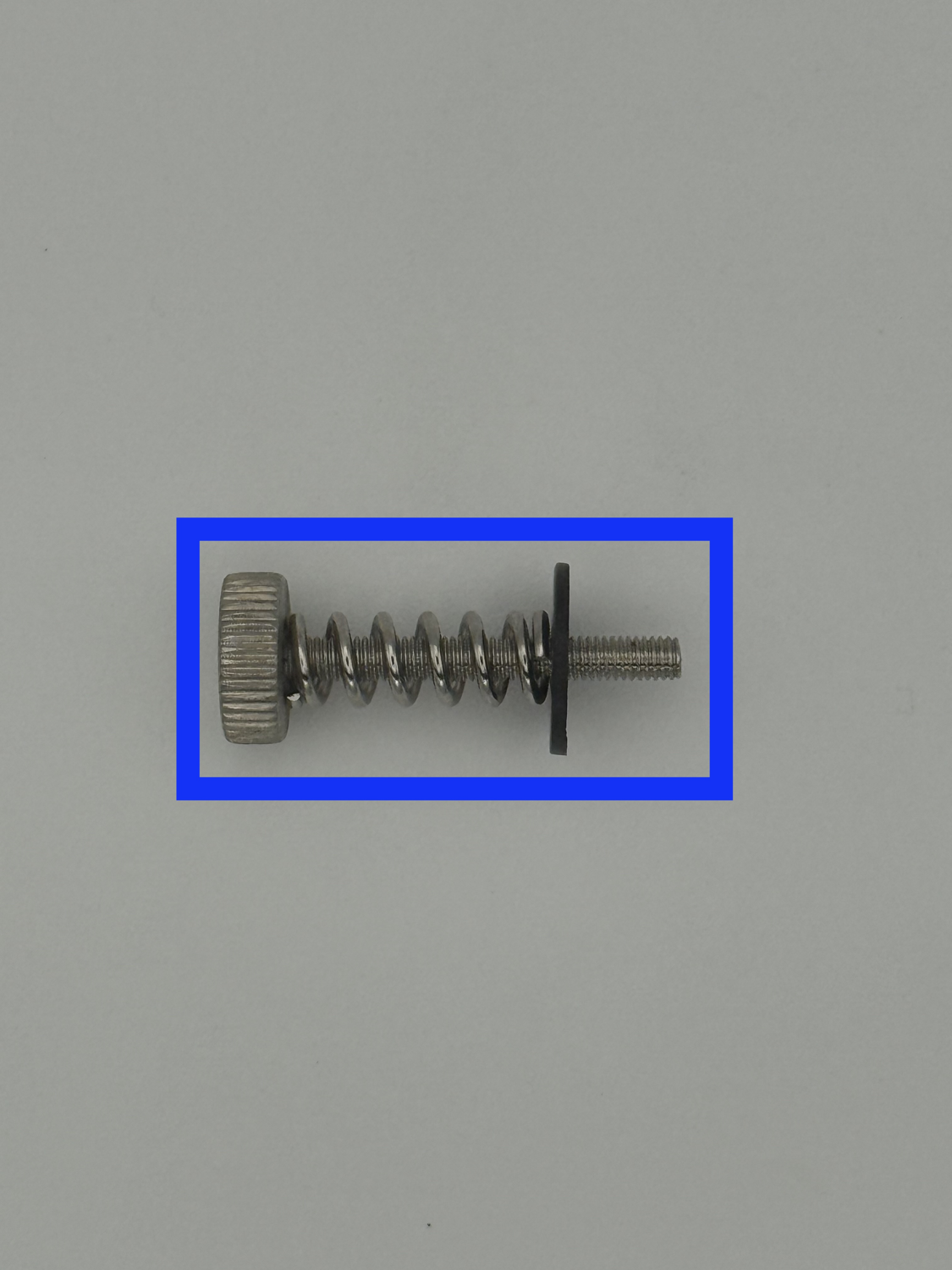
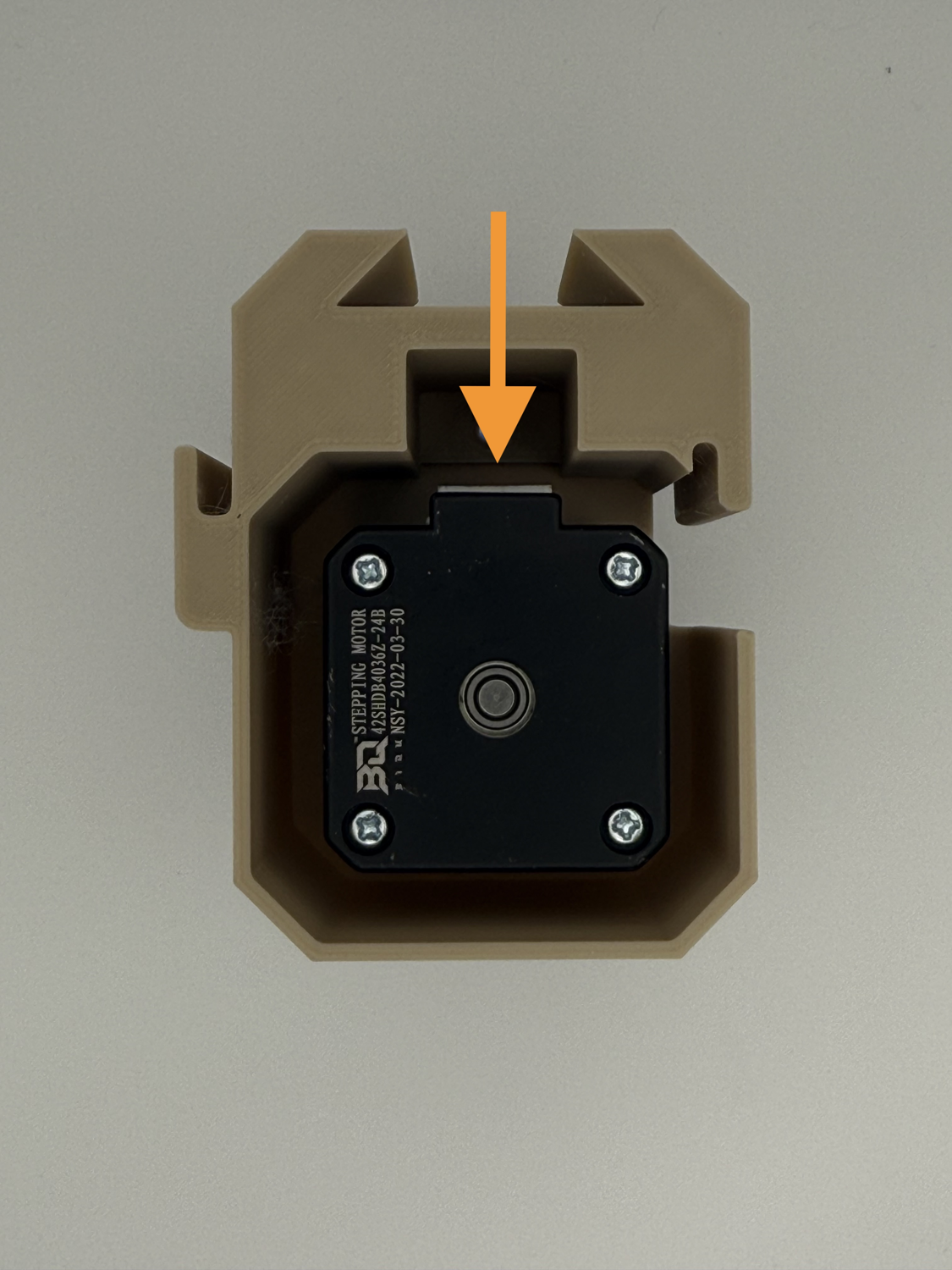
-
Prepare the following for this step:
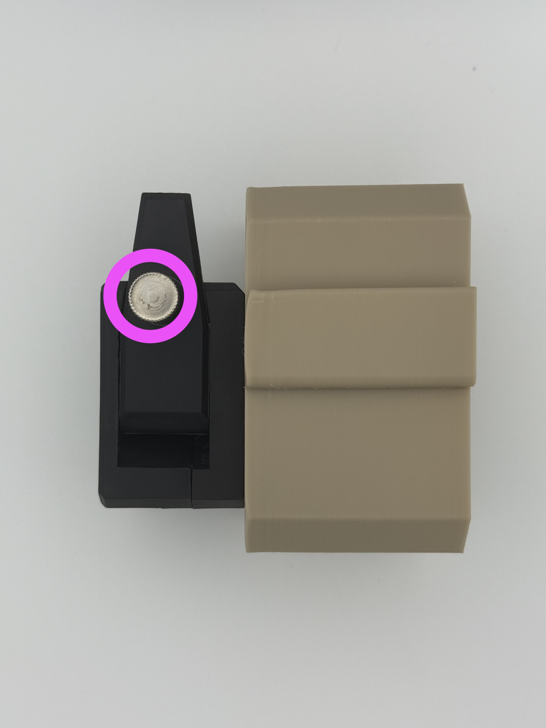
Tension screw (in extruder internals bag) Tension washer (in extruder internals bag) Tension spring (in extruder internals bag) Assemble the three as shown. Install the tensioner into the extruder through the hole on the side.
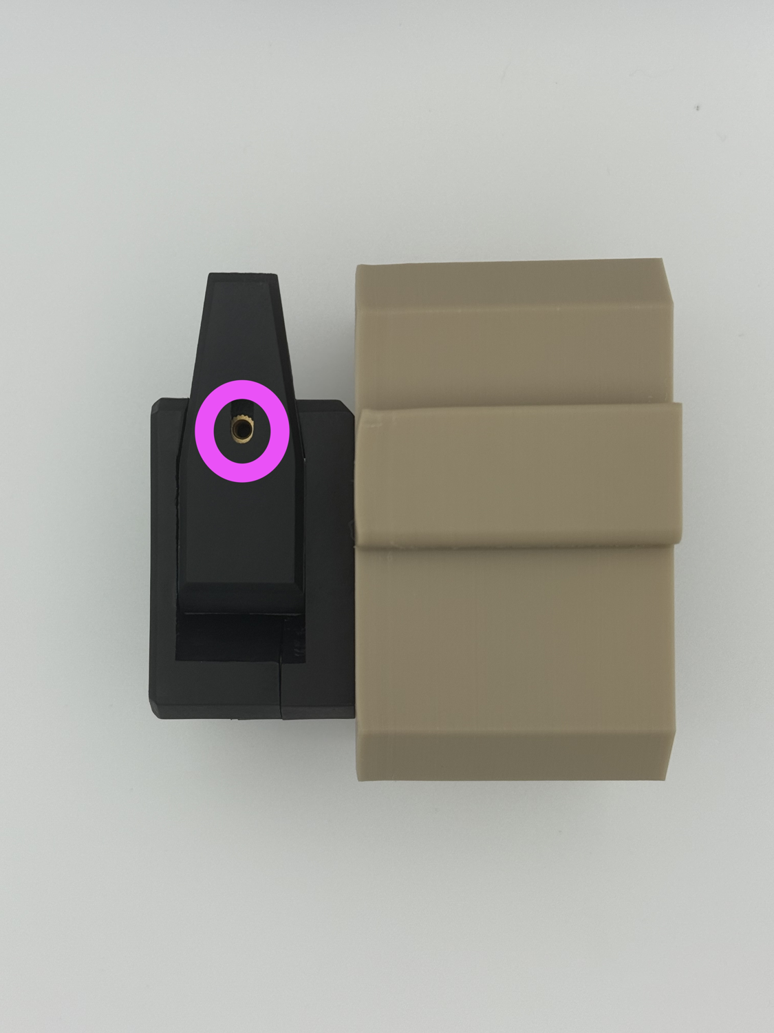
Step 7 Final Extruder Assembly
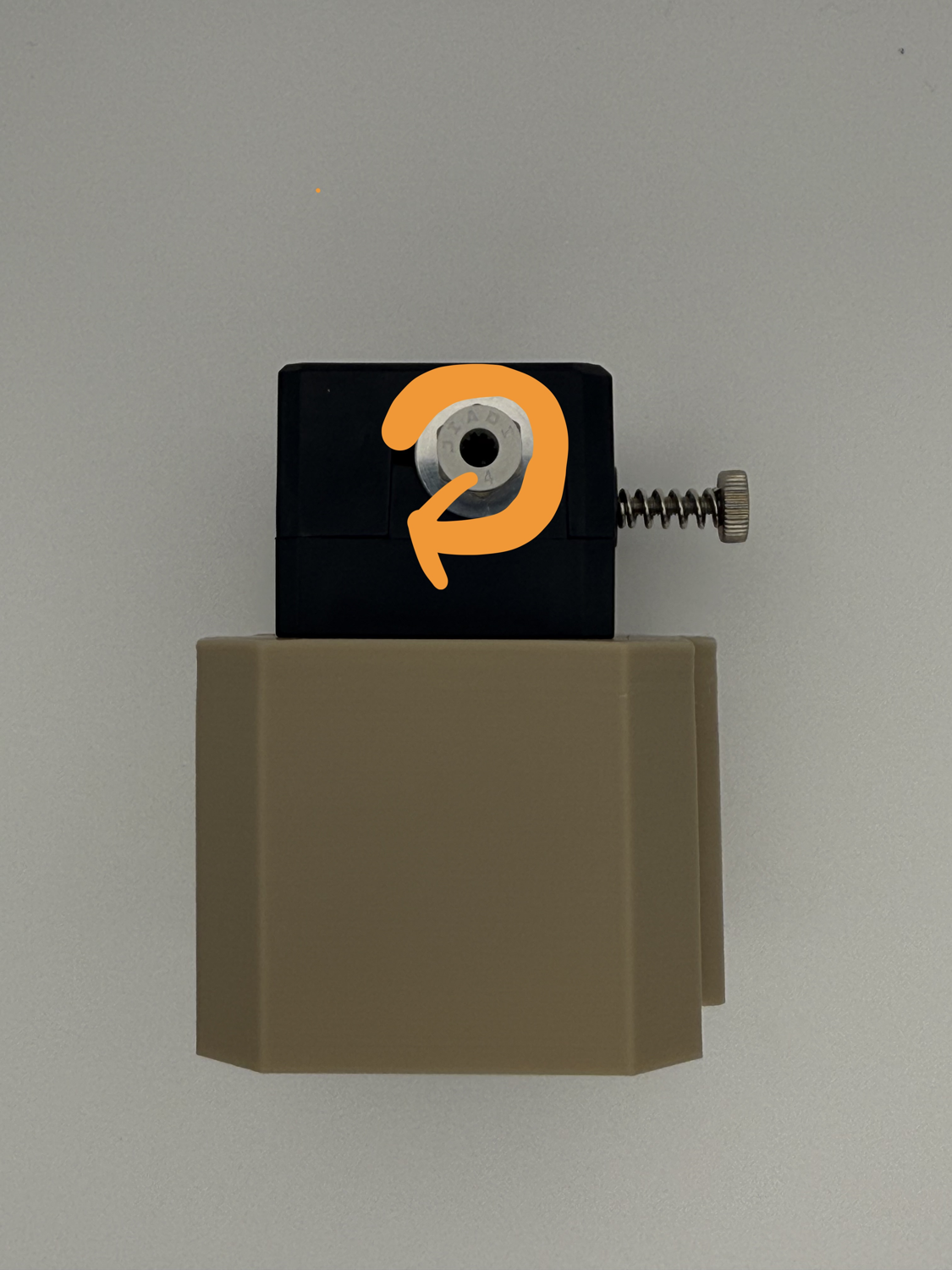
-
Prepare the following for this step:
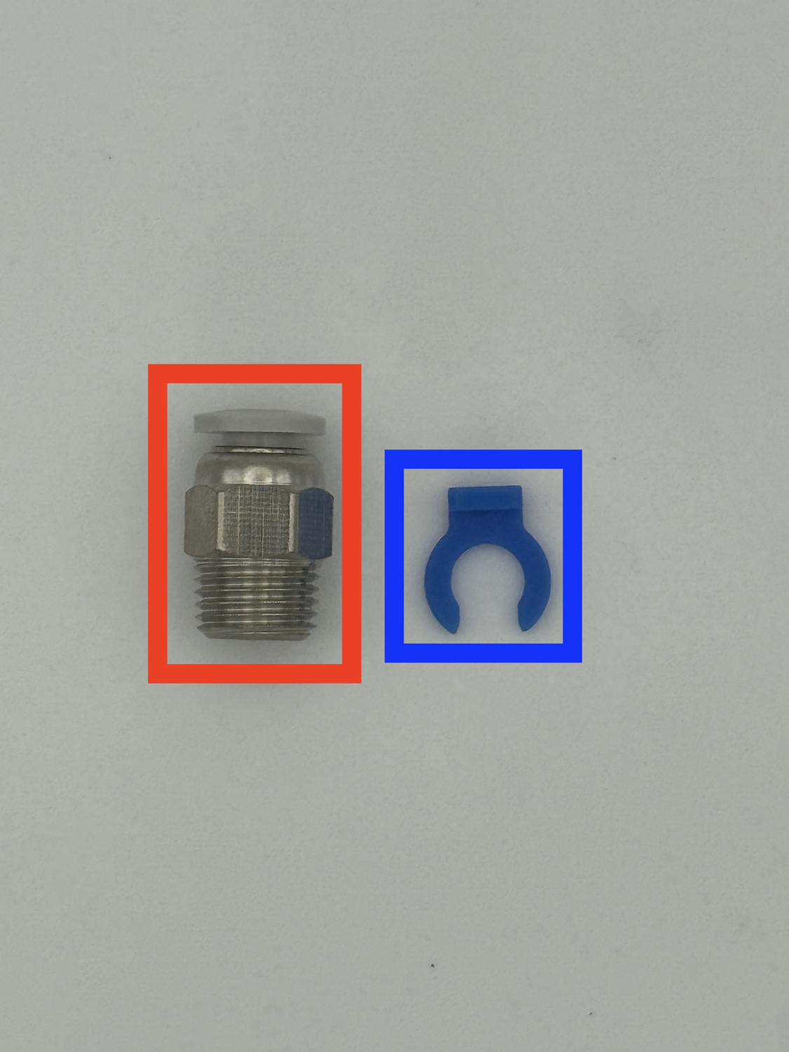
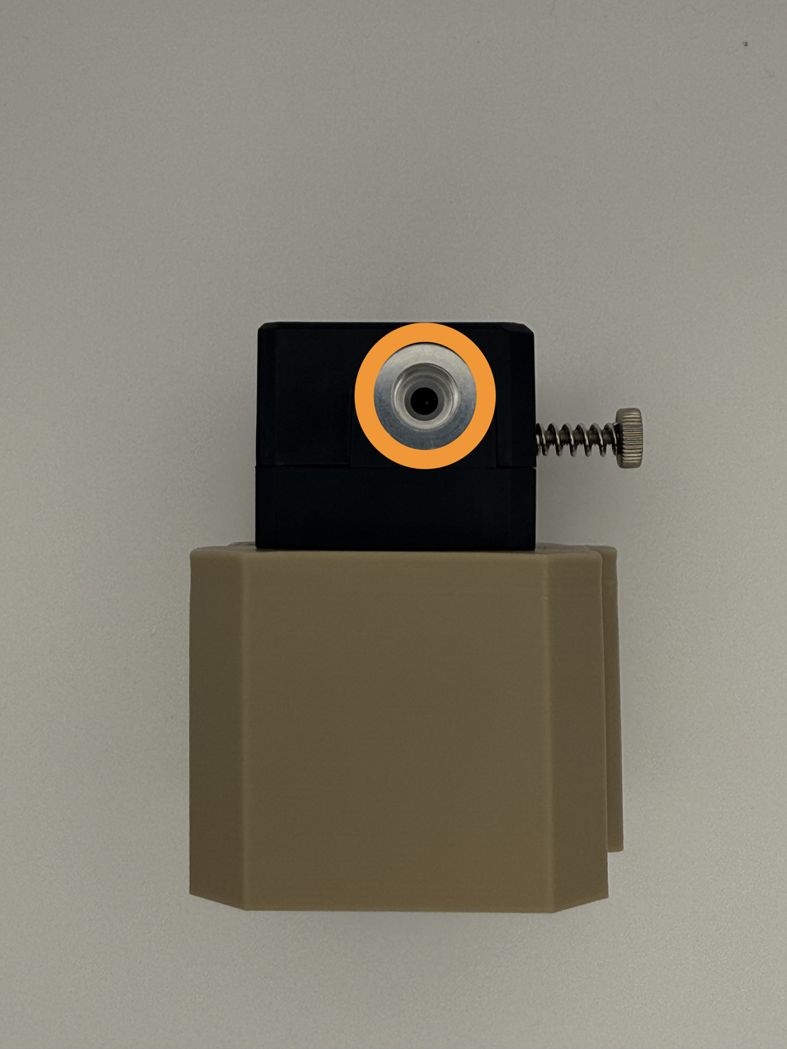
PC4-M10 fitting Blue Collet clip Locate the hole on the extruder and screw the PC4-M10 fitting into it. Insert the short length of PTFE into the ECAS fitting on the opposite end of the extruder.
Make sure to repeat this chapter a total of four times.
 You're done with extruders assembly!
Electronics Assembly
Step 1 Removing Supports: Part 1
-
Remove the built-in supports from the SKR Pico case.
Prepare either SKR Pico Bottom.stlorSKR Pico Bottom (small).stl(shown) Remove the indicated built-in support.
Step 2 Removing Supports: Part 2
-
Remove the built-in supports from the case.
Remove the indicated supports from the case.
Step 3 Installing the Board
-
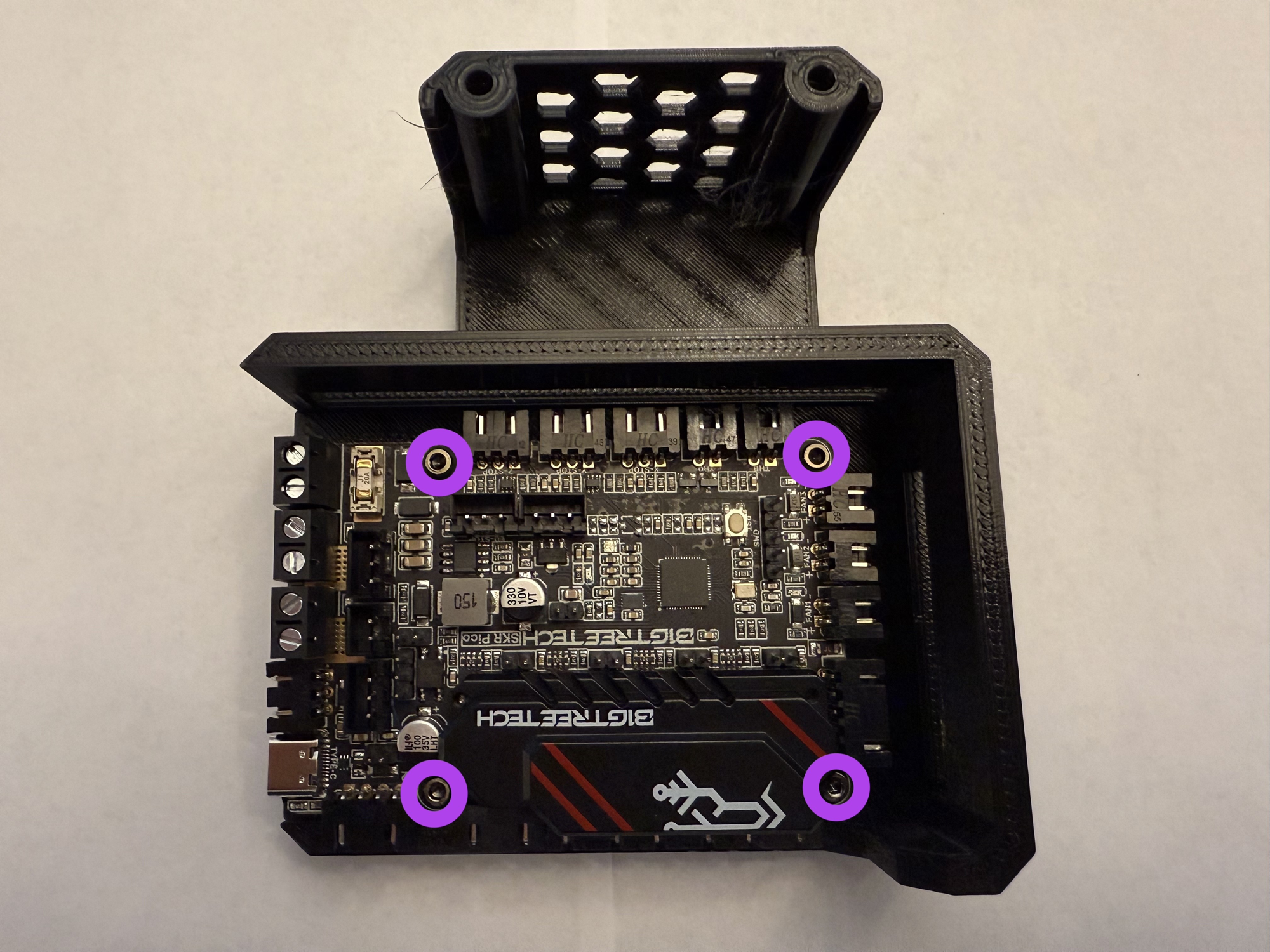
Install the SKR Pico board into the case.
Prepare the following for this step:
2mm Hex key 4x mounting bolts (included with the SKR Pico) SKR Pico board Place the SKR Pico board onto the previously prepared case. Using the four mounting bolts and the hex key, fasten the SKR Pico onto the case.
Step 4 Preparing the Power Cables
-
Strip the power cables and prepare for the next steps.
Prepare the following for this step:
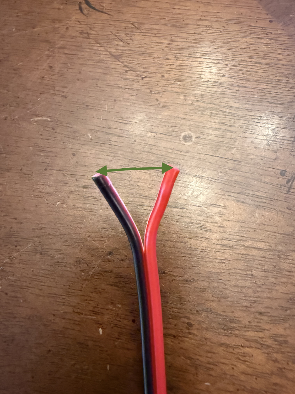
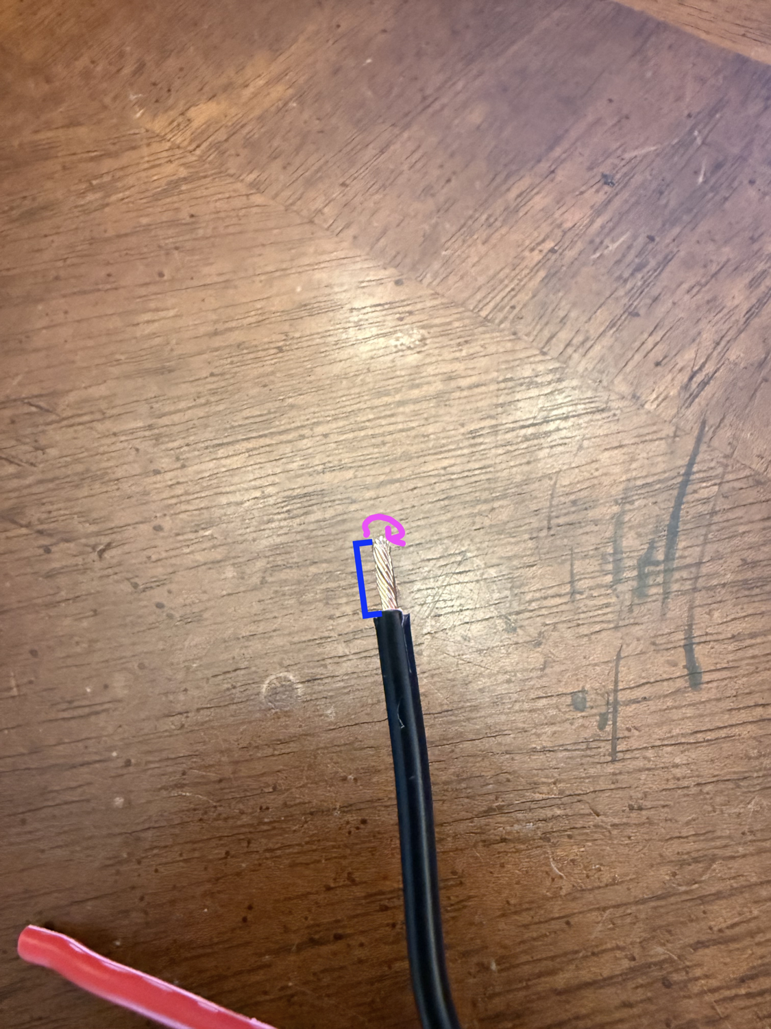
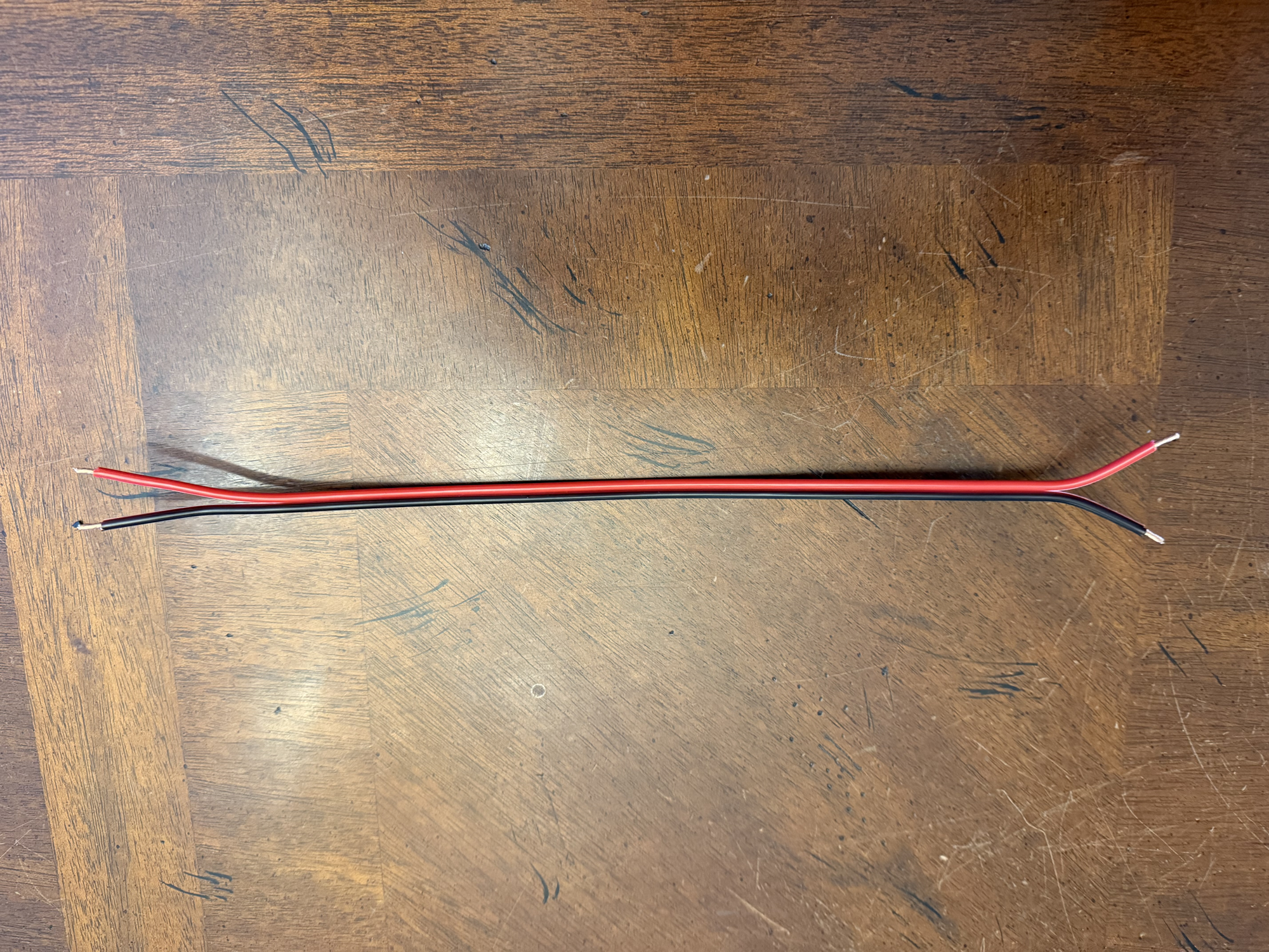
Power cables Wire strippers Split both ends of the wires as shown. Strip a short length off of all four ends of the wires. Twist the ends of the wires.
Step 5 Connecting the PSU
TODO...
Step 6 Connecting the Power Cables
-
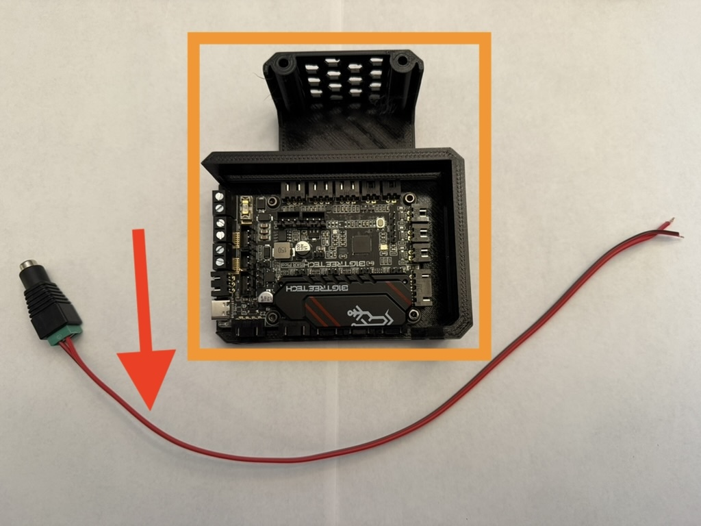
Connect the power cables from the PSU to the SKR Pico.
Prepare the following for this step:
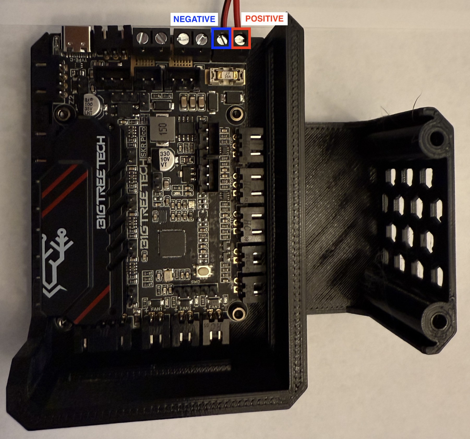
Power cables and PSU SKR Pico with caseFlat-head screwdriver
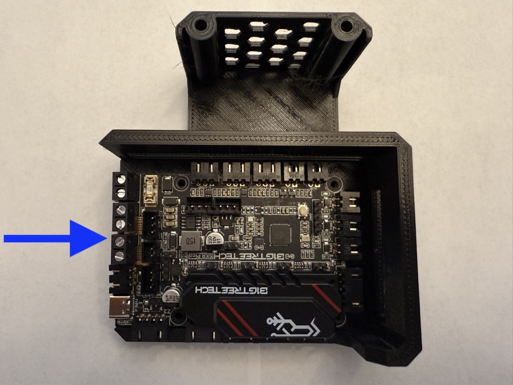
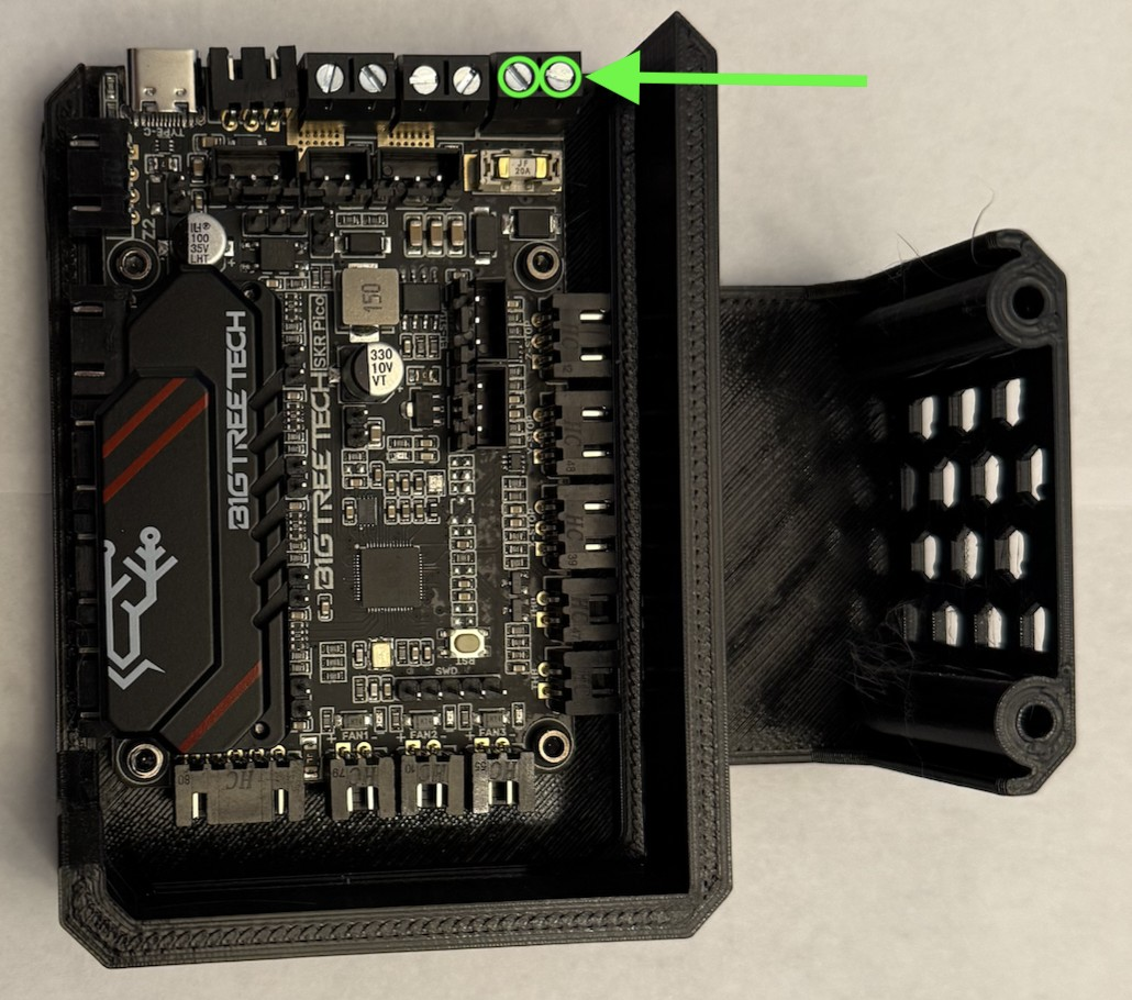
Loosen both power terminals on the SKR. Plug the red wire into the positive terminal on the SKR. Plug the black wire into the negative terminal on the SKR. Firmly tighten both power terminals on the SKR.
Step 7 Preparing the 3HOME
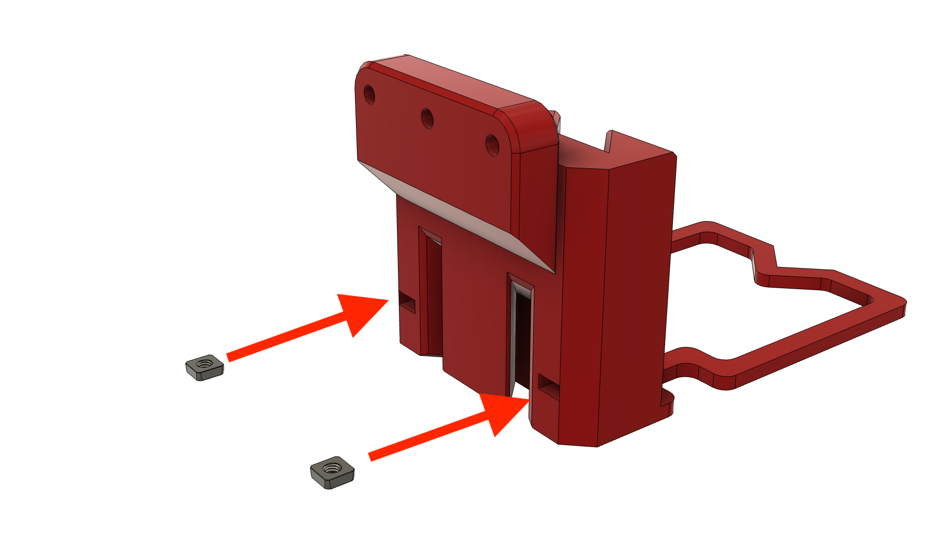
-
Add M3 square nuts to the 3HOME.
Prepare the following for this step:
-
3HOME
-
2x M3nS Square nuts
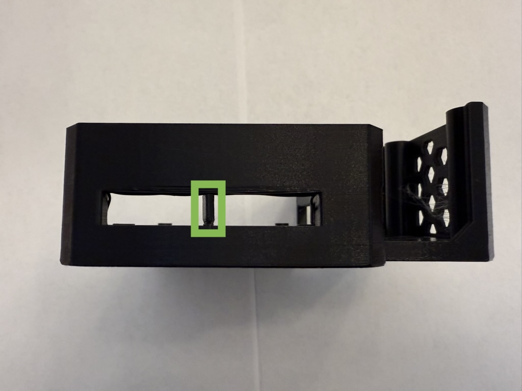
Insert the two square nuts into any joiner of the 3HOME -
Step 8 Attaching to the 3HOME
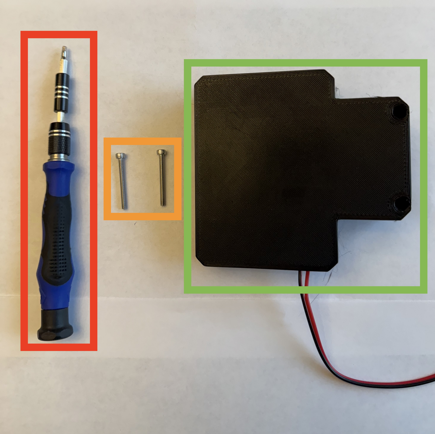
-
Attach the SKR Pico case to the 3HOME.
Prepare the following for this step:
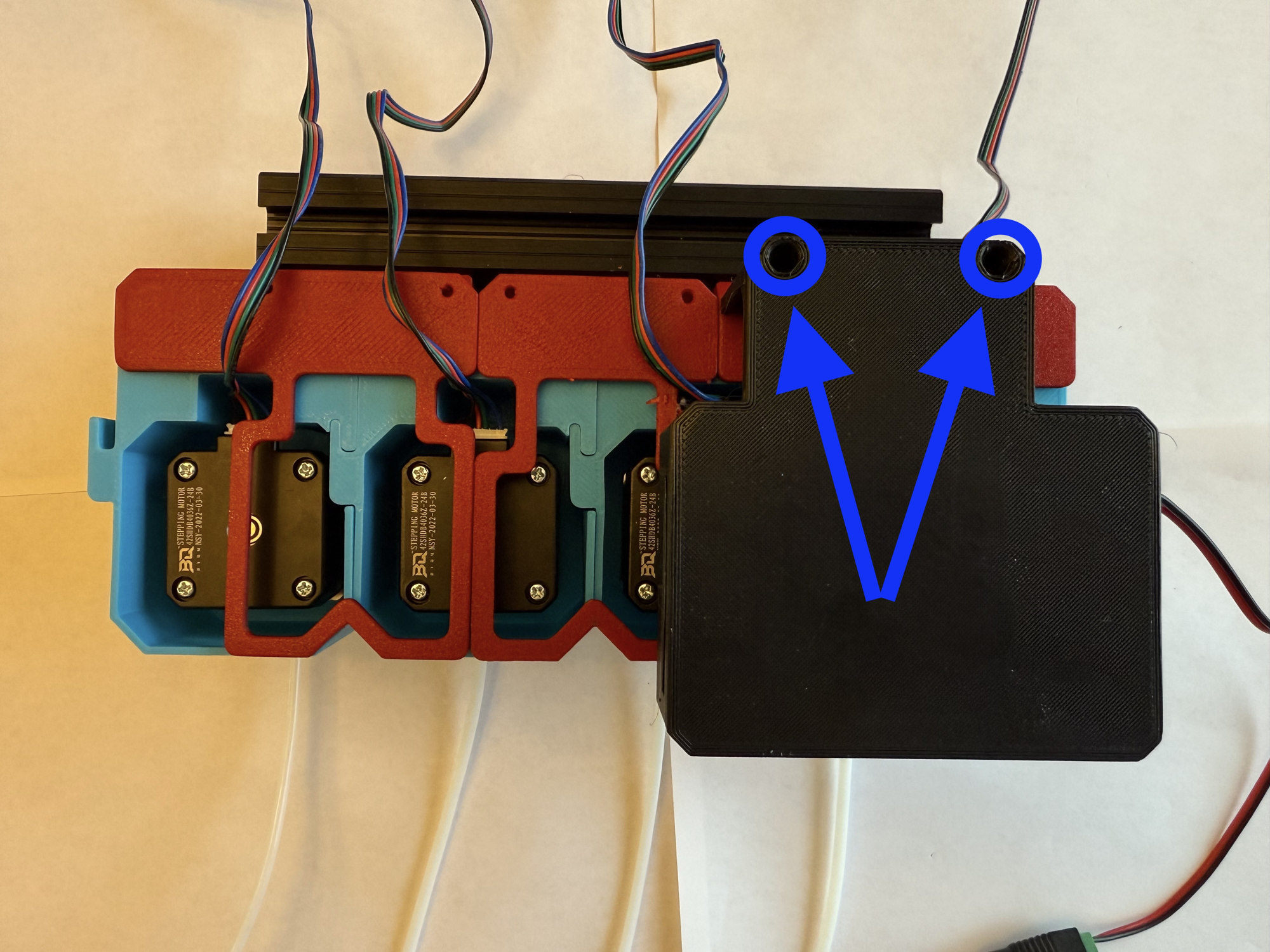
2.5mm Hex key 2x M3x30 SHCS SKR Pico case (prepared previously) Fasten the SKR Pico to the 3HOME with the two M3x30 SHCS using the 2.5mm hex key.
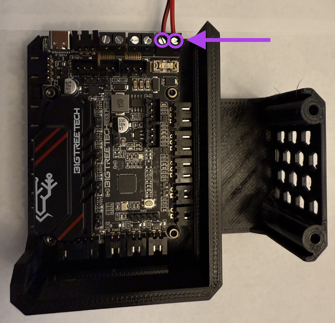
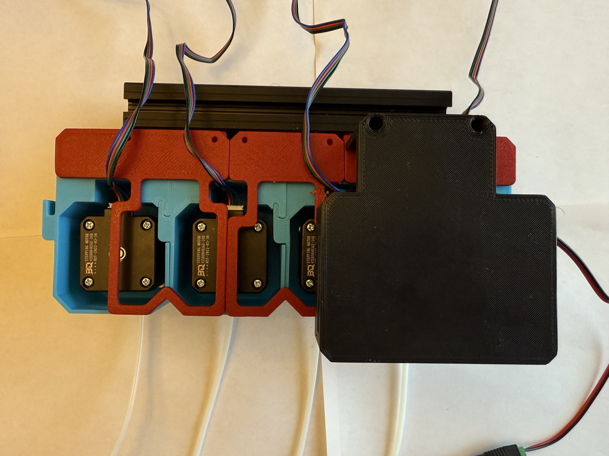
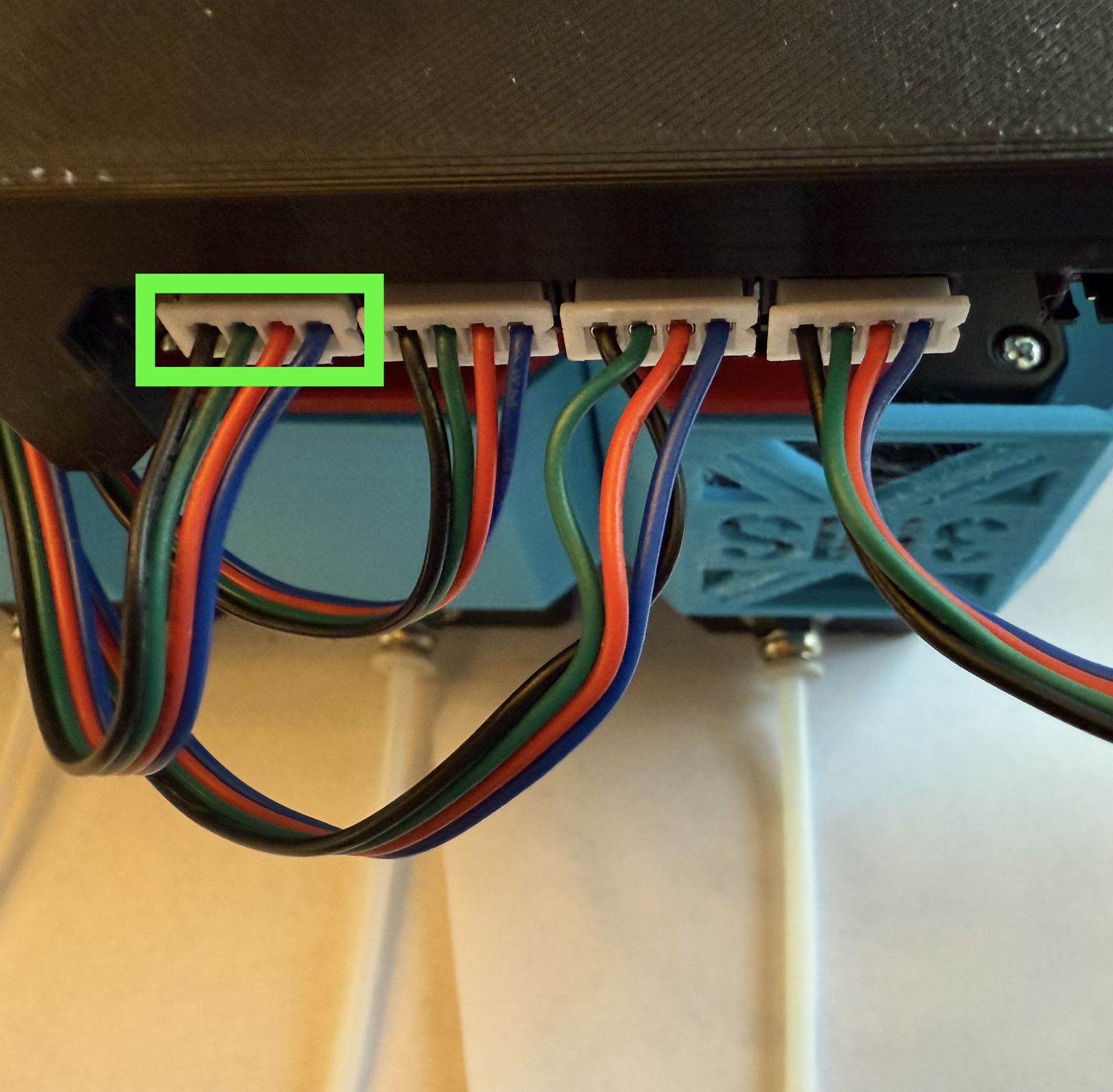
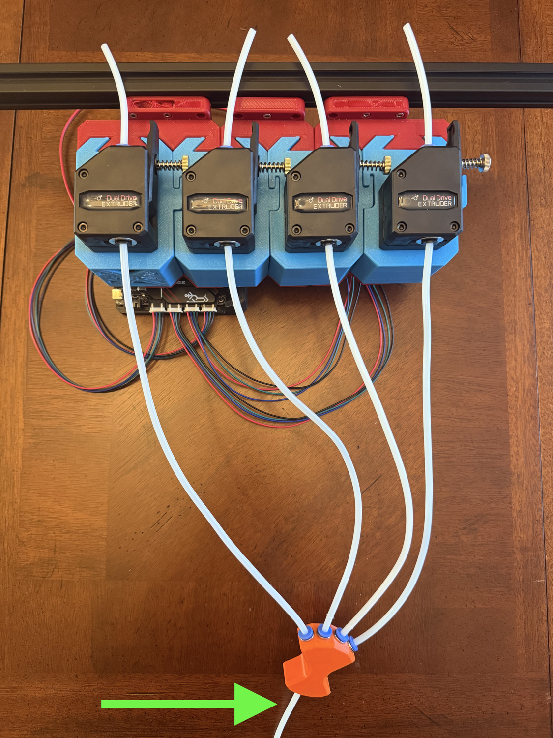
Step 9 Wire Management
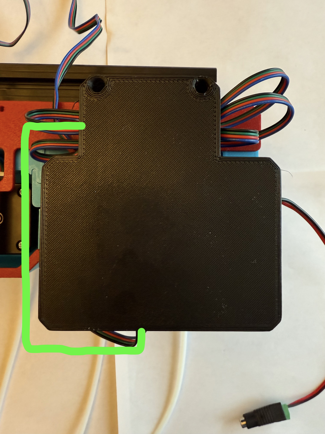
Begin by stretching out each stepper motor wire away from the 3HOME as shown.
Next, take the rightmost wire (T0) and form it into the shape shown.
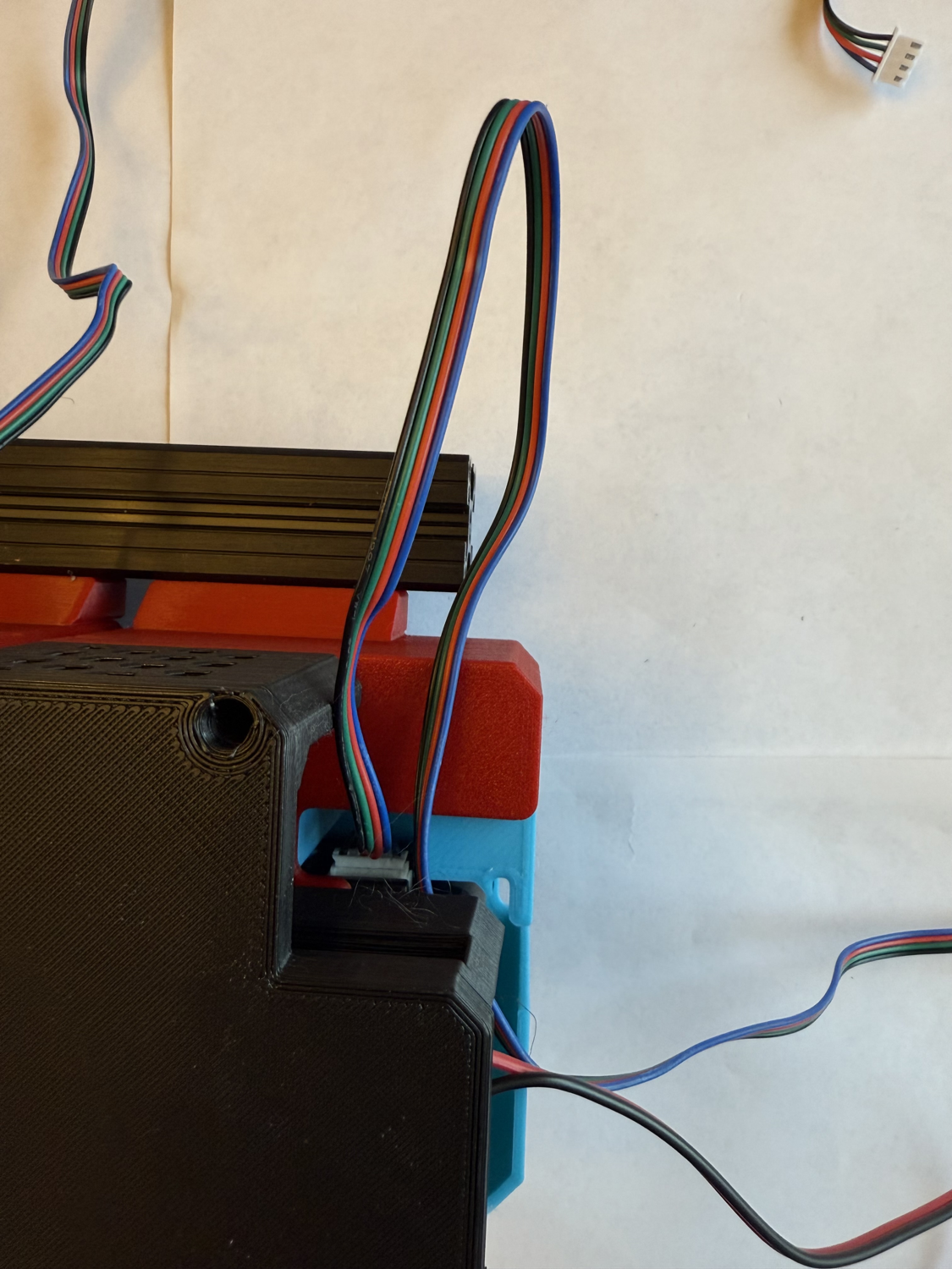
Fold it back over itself several times until a short length is remaining. Use a zip tie to secure and cut off the excess from the zip tie.
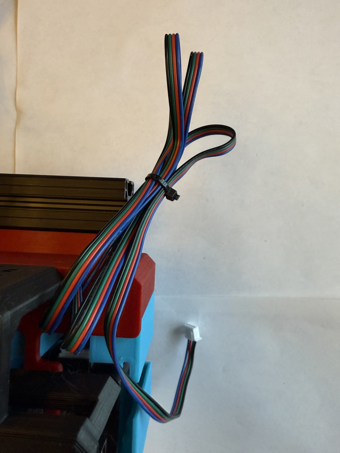
Push the cable bundle into the SKR case and route the wire as shown with the green line.
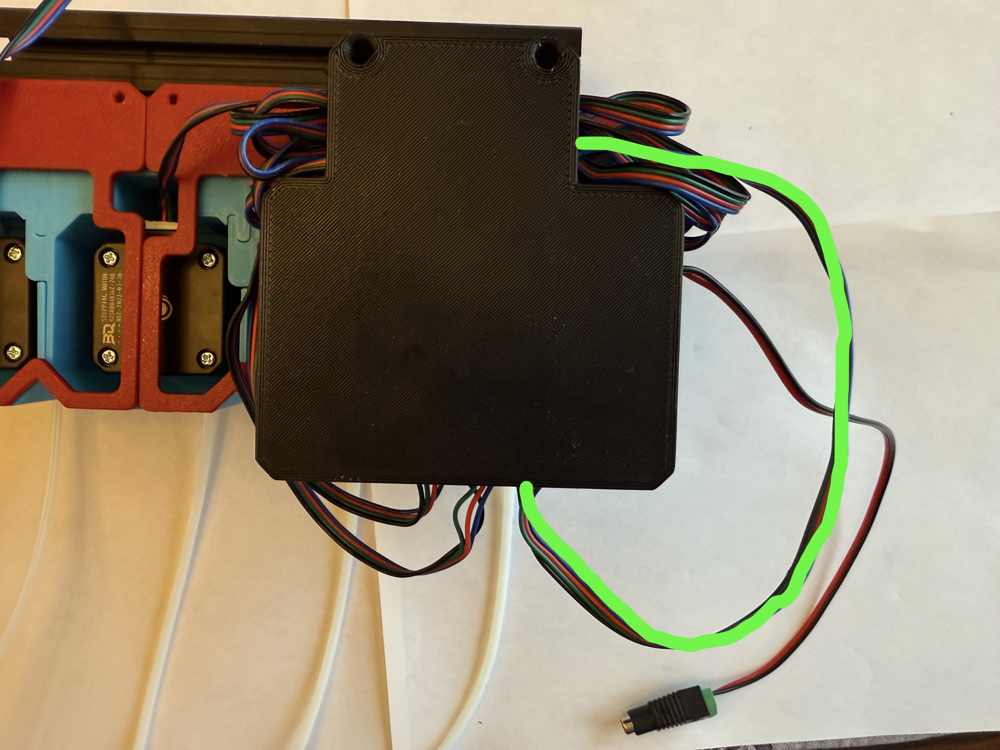
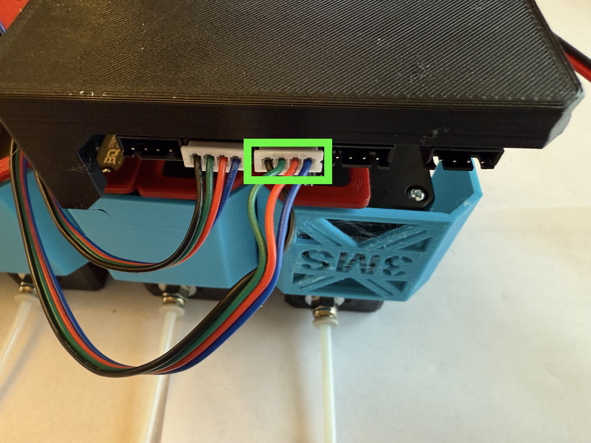
Plug the stepper cable into the second-to-left port on the SKR (when viewed upside down as shown)
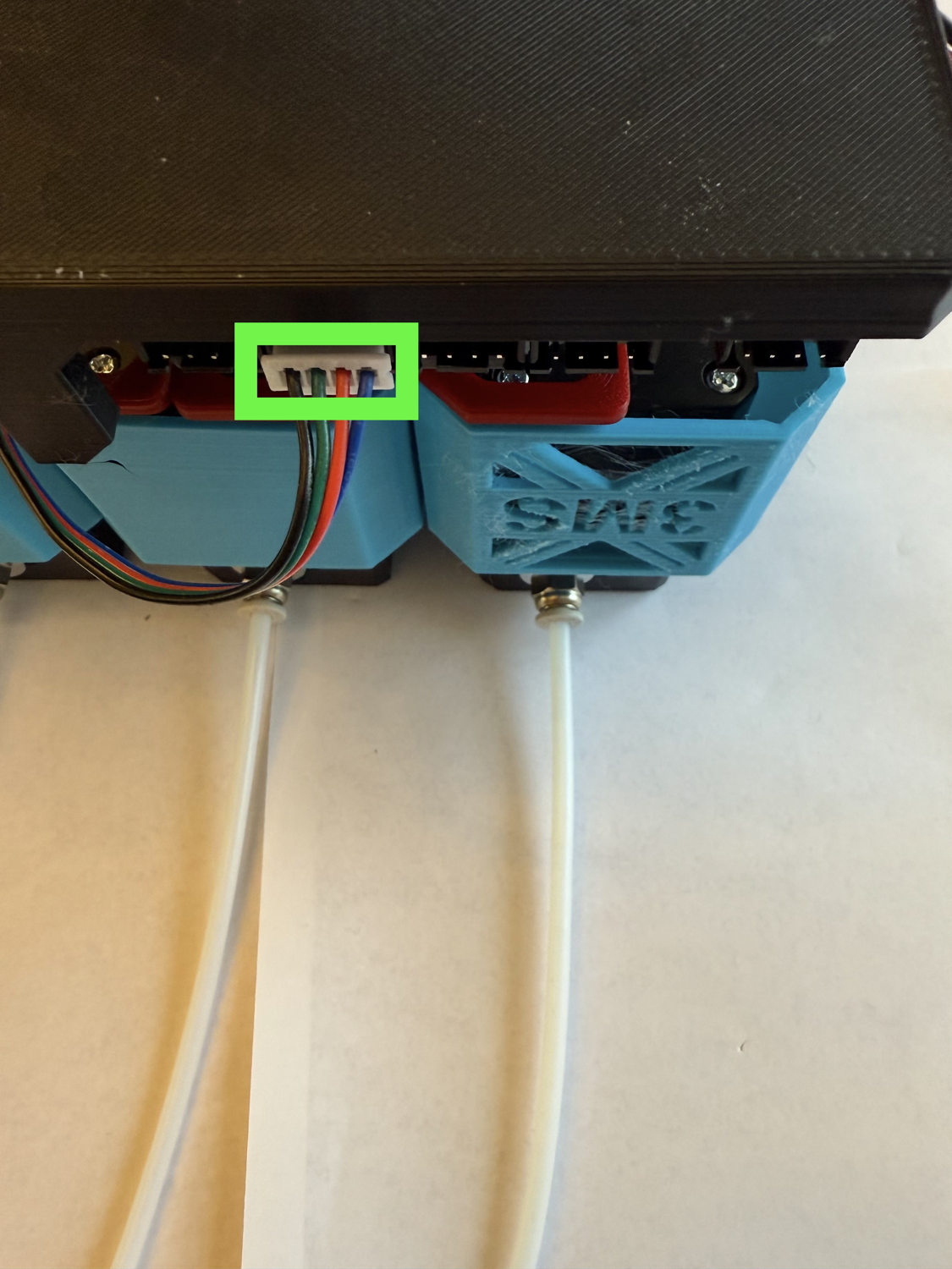
Repeat the same process for the stepper motor to the left of the previous one. Plug it into the port to the right of the first one.
Repeat the process for the next stepper motor in line, routing the wire as shown with the green line.
Plug the stepper into the port to the right of the previous one.
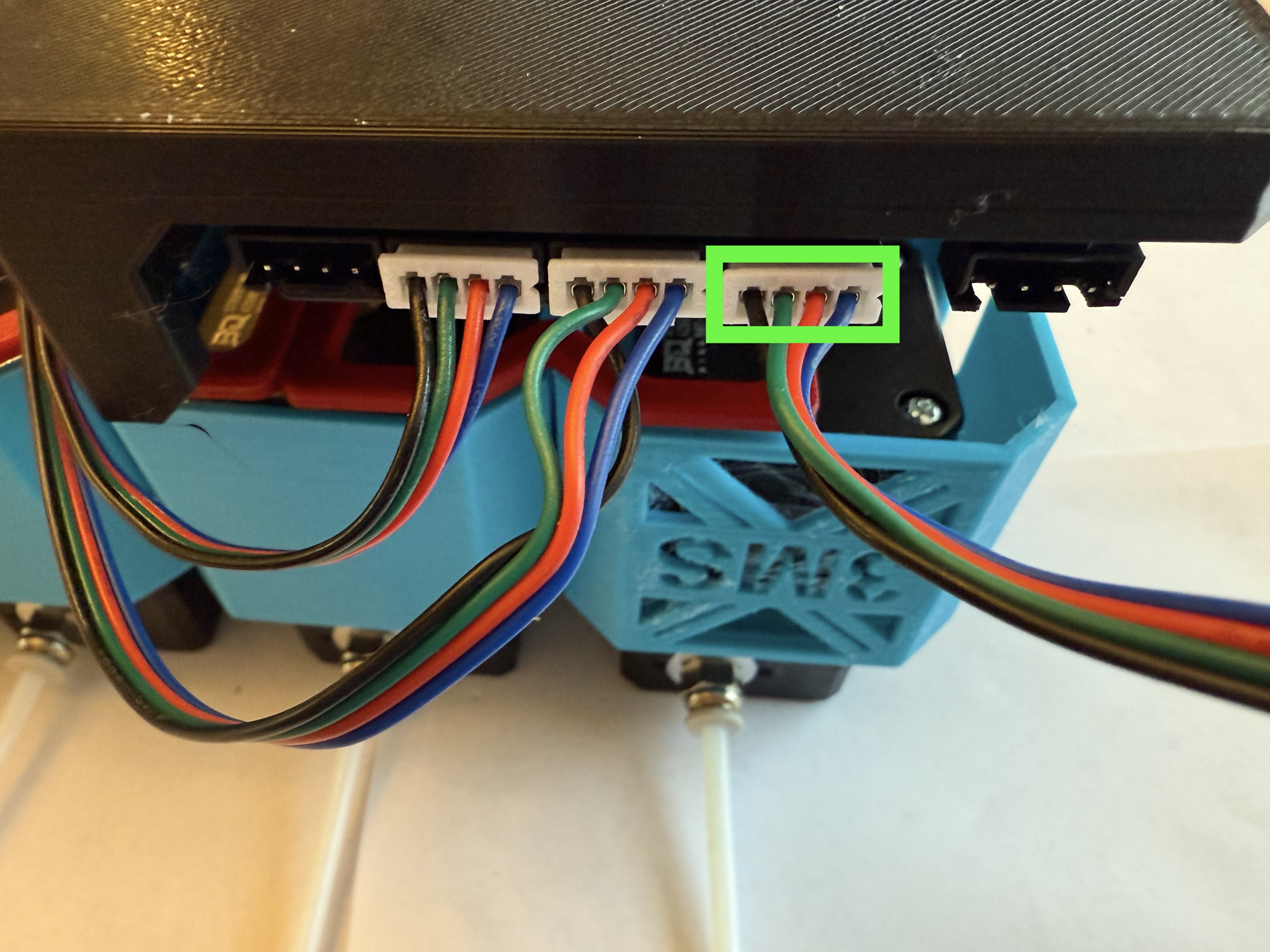
Repeat the process for the final stepper, routing the wire as shown with the green line.

Plug this stepper into the leftmost plug on the SKR.
You're done with electronics assembly!
Final Assembly
You're almost done with assembling your 3MS! Follow this guide to finish the hardware side of assembly.
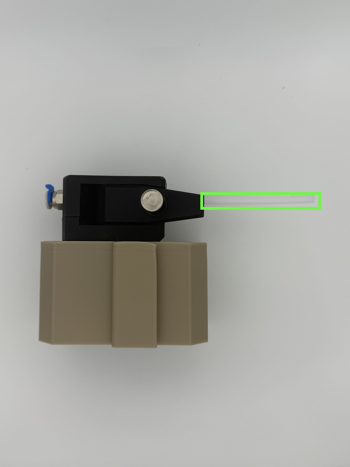
Step 1 Preparing the PTFE Tubing
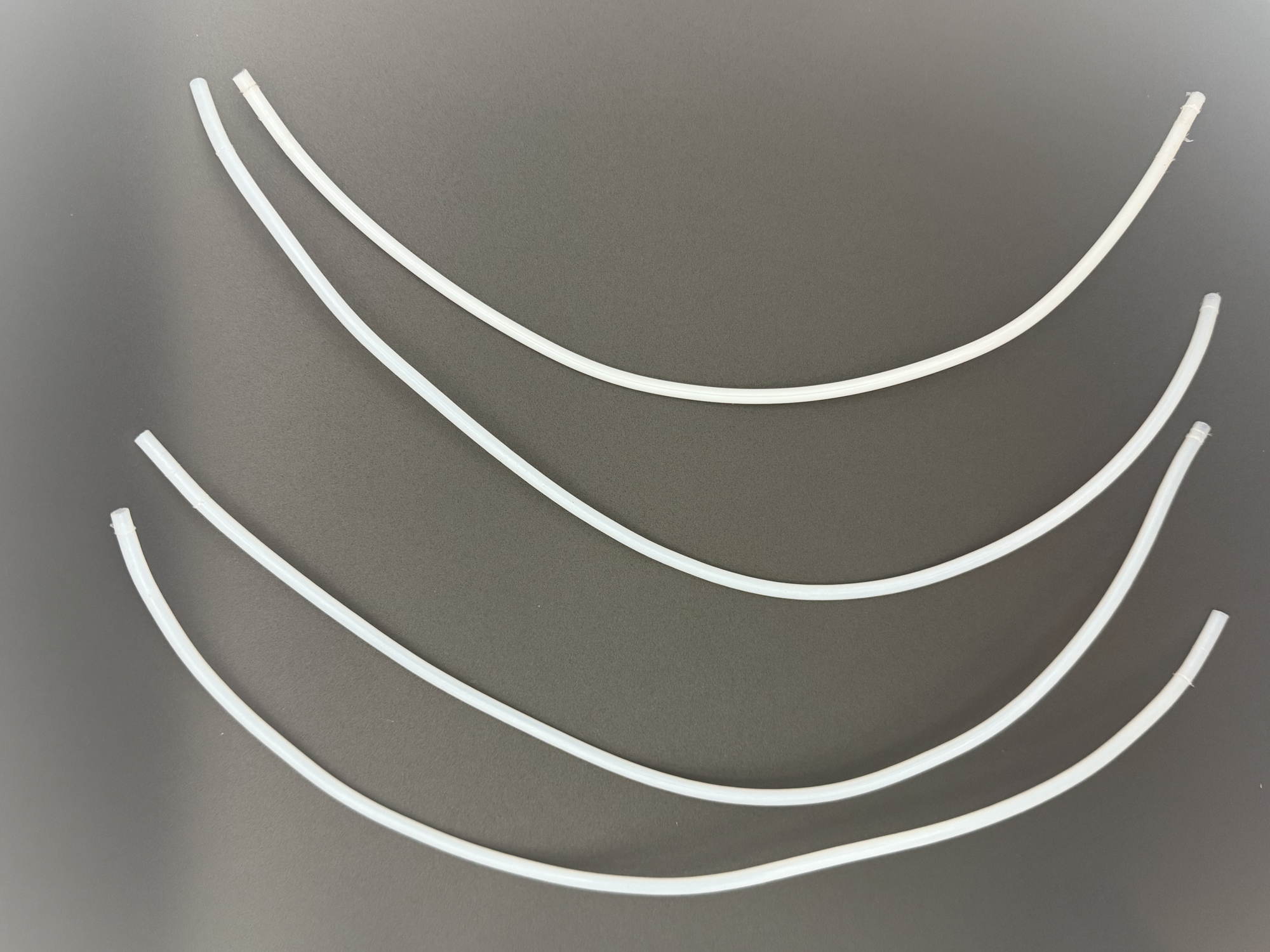
- Cut four equal-length segments of PTFE tubing. These should each be long enough to almost reach from the 3MS to your printer's extruder.
Step 2 Inserting the PTFE Tubing
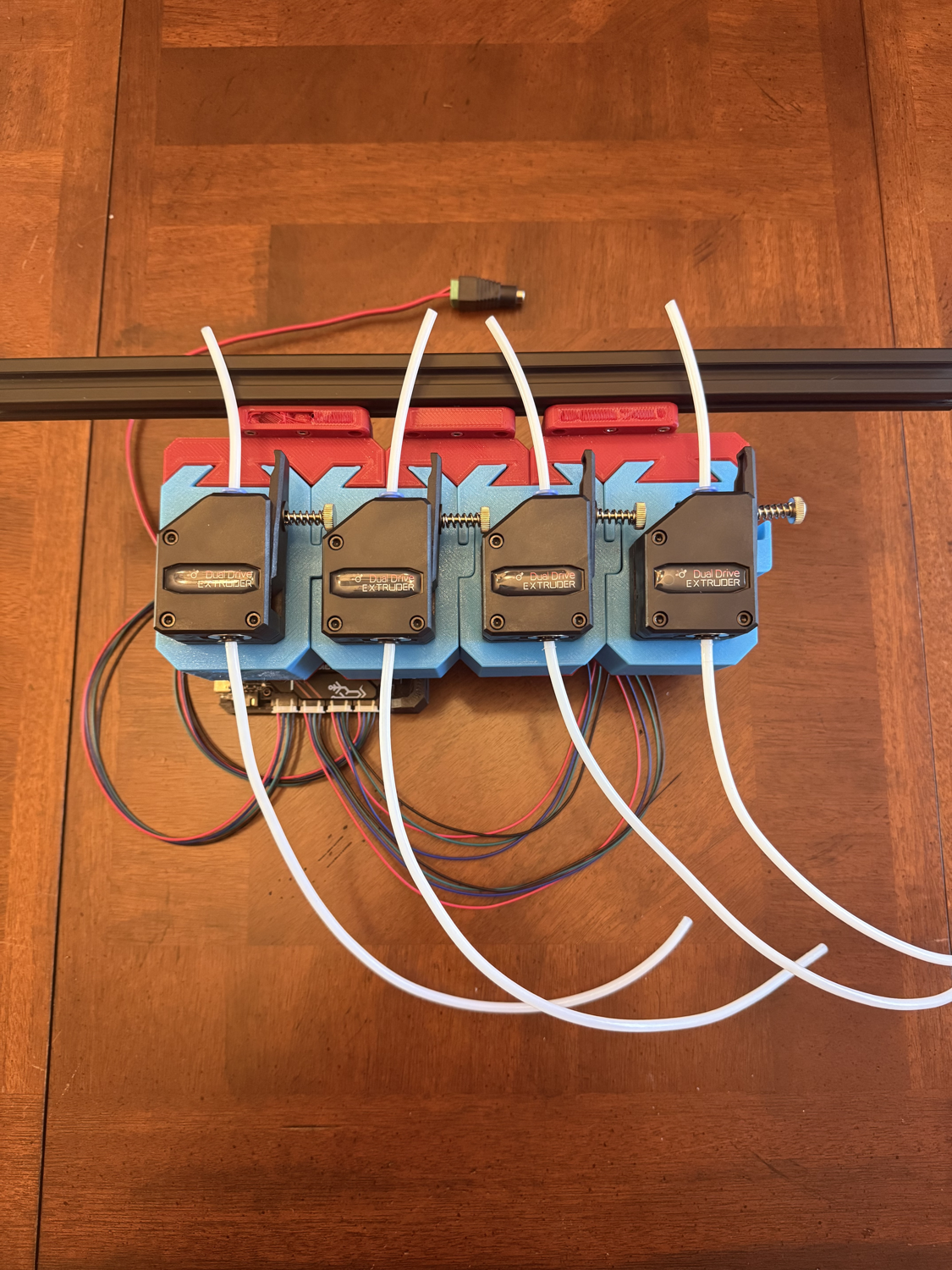
- Insert all four segments of PTFE tubing into each of the four filament units.
Step 3 Installing the Y-splitter
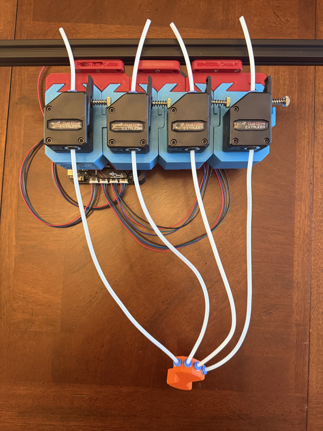
- Insert the other end of each of the four segments of PTFE into the Y-splitter.
Step 4 Tubing to the Extruder
- Insert the remaining PTFE tubing into the other end of the Y-splitter. Cut to the proper size to reach your printer's extruder.
You're done building your 3MS!
Please go to Controllers to flash firmware for your control board.
https://github.com/moggieuk/Happy-Hare/wiki/Quick-Start-3MS
Konfiguration
Nach dem Installieren der Happy Hare Firmware musst du ein paar Einstellungen vornehmen, bevor du mit mehreren Materialien drucken kannst.
Filament Sensoren
Um das 3MS nutzen zu können brauchst du einen Filament Sensor. Angenommen du hast bereits einen eingebaut, kannst du ihn in mmu_hardware.cfg konfigurieren.
Du findest ihn im [mmu_sensors]-Abschnitt kurz vor dem Ende der mmu_hardware.cfg.
Extruder/Werkzeugkopf Sensoren
Um einen Extruder-Eintrittssensor (ein Sensor direkt vor deinem Extruder) zu konfigurieren, setze deinen extruder_switch_pin:
Du kennst weißt deinen Sensor Pin nicht?
Falls du deinen Sensor Pin nicht kennst und er schon in Klipper eingerichtet ist, dann kannst du ihn in deiner Sensor Konfiguration (normalerweise als filament_switch_sensor) finden und dir den sensor_pin notieren.
Um einen Werkzeugkopfsensor (ein Sensor direkt nach deinem Extruder) zu konfigurieren, setze deinen toolhead_switch_pin auf die gleiche Weise wie den extruder_switch_pin.
Gemeinsamer Gate Sensor
Vom der Düse aufwärts gesehen, ist der nächste mögliche Sensor ein gemeinsamer Gate Sensor. Der sitzt direkt hinter dem Y-Sülitter (vom 3MS aus gesehen).
Falls du einen Gate Sensor verwendest setze gate_switch_pin:
Pre/Post Gate Sensors (Optional)
Falls du einen Filament-Sensor vor oder nach jeder deiner 3MS Filament-Einheiten hast, konfiguriere einen pre_ oder post_gate Sensor.
Pre-Gate
Pre-Gate Sensoren sitzen vor jeder deiner Filament-Einheiten. Konfiguriere sie wie folgt:
| mmu_hardware.cfg | |
|---|---|
Post-Gate
Post-Gate Sensoren sitzen hinter jeder deiner Filament-Einheiten. Konfiguriere sie wie folgt:
| mmu_hardware.cfg | |
|---|---|
Existing Sensors
Bevor du weitermachst, stelle sicher, dass all deine existierenden filament_switch_sensor und filament_motion_sensor Abschnitte auskommentiert oder gelöscht sind. Sie aktiv zu lassen würde später zu Problemen führen.
Entfernungen
In der Happy Hare Firmware gibt es viele wichtige Entfernungen zu konfigurieren. Alle Entfernungs-Parameter sind in mmu_parameters.cfg zu finden.
Endstop Homen
Wennn du die Filamentposition homen willst, hast du drei Optionen für den zu verwendenden Sensor:
- mmu_gate Verwende den gemeinsamen Gate Sensor nach dem Y-Splitter.
- mmu_gear verwende die jeweiligen Post-Gate-Sensoren.
- extruder Verwende den Extruder-Eingangssensor.
Wähle eine dieser Optionen aus und setze sie als gate_homing_endstop, in der mmu_parameters.cfg.
Homing Entfernung
Als nächstes konfigurierst du die maximale Strecke die Happy Hare Filament zum Homing Sensor schieben soll, bevor er "aufgibt" und die Spule als "leer" meldet. Diese Länge sollte gewöhnlich ca 150% der Distanz von der Filament-Parkposition zum Filament-Sensor entsprechen.
Anmerkung
Falls du Post-Gear Endstops (mmu_gear) verwendest, wird der gate_preload_homing_max Parameter verwendet.
Dieser Parameter heißt gate_homing_max.
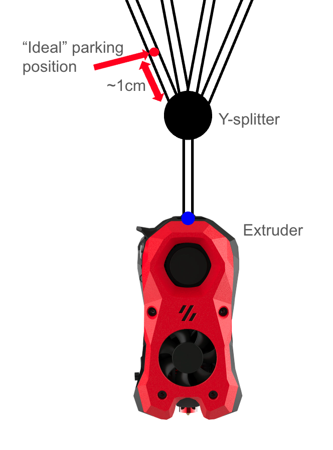
Parkposition
Das ist die Position an der dein Filament warten soll, wenn es nicht verwendet wird (gemessen vom Gate-Endstop). Sie sollte ungefähr 1-2cm oberhalpt deines Y-splitters liegen.
Dieser Parameter heißt gate_parking_distance.
Ausgabeentfernung
Abschließend, falls du Filament in einer Filament-Einheit mit einem anderen Filament austauschen willst, editiere gate_final_eject_distance. Sie sollte der Entfernung von deiner Parkposition zur Filament-Einheit entsprechen, plus einer kleinen Strecke.
Geschwindigkeiten
Es gibt viele verschiedene Geschwindigkeiten, die du in der Happy Hare Firmware konfigurieren kannst.
Du findest sie im "speeds"-Abschnitt der mmu_parameters.cfg (nahe des Anfangs).
Homing Geschwindigkeit
"Homing" ist wenn Happy Hare Filament zu deinem oben ausgewählten Filament-Endstop schiebt, um sicherzustellen, dass Filament vorhanden ist. Du kannst die verwendete Geschwindigkeit anpassen, indem du den gear_homing_speed Parameter anpasst.
"First Load"-Geschwindigkeiten
Happy Hare erlaubt dir das erste Laden eines Filaments langsamer zu ausführen zu lassen um zusätzlichen Wiederstand durch die Spule auszugleichen. Um diese Geschwindigkeit anzupassen, editiere gear_from_spool_speed.
Be- und Entladegeschwindikeiten
Um deine Be- und Entladegeschwindikeiten während eines Werkzeugwechsels anzupassen, editiere den gear_from_buffer_speed Parameter.
Calibration
Follow this guide to calibrate your 3MS.
Original Documentation
This guide is a simplified version of the official Happy Hare documentation. I highly recommend you read it as it contains useful information and goes more in detail if you are having trouble with the calibrations.
Verify Filament Sensors
Before calibrating, it is important to ensure that your filament sensors are working properly.
Run in your Klipper console:
and verify the output. For each endstop, open means no filament detected, and TRIGGERED means filament present. Re-run the command several times, inserting/removing filament to each of the sensors, to verify that each filament sensor properly detects filament.
Gear Steppers
First, calibrate your gear steppers (filament units). The goal of this calibration is to ensure the filament actually moves as far as expected.
First, detach the PTFE tubing from each of the filament units.
For each filament unit (gate), repeat the following steps:
- Manually load filament until it sticks out slightly from the end of the filament unit
- Cut the tip of the filament to be flush with the PTFE coupler (side cutters are good for this).
-
Run the following commands in your Klipper console:
where
nis the gate number you are calibrating (starting at zero). -
The filament should move forwards. If it moves backwards, invert your gear stepper. Measure the distance the filament moved out of the extruder. Using side cutters the same as before can be helpful for this. Run the following command in your Klipper console:
where
nis the measured distance. -
Repeat step 3. The filament should move exactly
100mm.
Configuring the Parking Position
The parking position is the location your filament should park when idle, measured from your gate endstop. This should be set to ~1-2cm above your Y-splitter.
This parameter is called gate_parking_distance in mmu_parameters.cfg.
To determine this value, begin by moving the filament in gate 0 to the ideal parking position by hand.
If you have an extruder entry sensor configured, determining your parking distance from here is super easy.
Run the following commands in Mainsail:
Operation not possible. MMU has filament loaded
If Mainsail reports this error after trying to select a gate, run the following command to tell HH that filament is not loaded.
Note the distance displayed.
Read your toolhead_entry_to_extruder value from mmu_parameters.cfg.
Set your gate_parking_distance to:
To tune this value, start by estimating the distance from your extruder to the ideal parking position. You can use a piece of filament outside of the tube and use a ruler to help measure this. In the diagram above, it's the distance between the red and blue dots.
Set this starting value in mmu_parameters.cfg:
Run the following commands in Mainsail:
Operation not possible. MMU has filament loaded
If Mainsail reports this error after trying to select a gate, run the following command to tell HH that filament is not loaded.
The filament should load to the extruder then unload to the parking position.
If it unloaded to the correct spot (around the red dot), then your parking distance is good.
If not, use the below command to move the filament until it's at the correct position (positive is towards the extruder, negative is away from it):
Finally, run MMU_STATUS and note the "UNLOADED" value shown.
Save the shown value as your parking distance.
Encoder (if installed)
If you are using an encoder, like a BTT SFS (Smart Filament Sensor), you need to calibrate your encoder.
- Load your filament manually to its parking position at the start of the Y-splitter.
-
Run in your Klipper console:
Inverting a Gear Stepper
If you notice any of your gear steppers moving filament in the opposite direction as expected, you need to invert the gear stepper. There are two options to do this:
- Physically flip the stepper cables
- Invert it in software
To invert a gear stepper in software, open mmu_hardware.cfg and invert the dir_pin for the respective stepper.
Example, if T1 is moving backwards:
Tip
If the pin already has a ! in front of it, remove it to invert it.
Restart Klipper.
First Print
Congratulations on building your 3MS! Now to get started with a first print.
Slicer Setup
This tutorial will walk you through setting up the 3MS with OrcaSlicer. If you use another slicer, some settings may differ.
Credit
This tutorial is based off of the original Happy Hare slicer setup docs, available here.
Machine Settings
Begin by opening your machine settings.
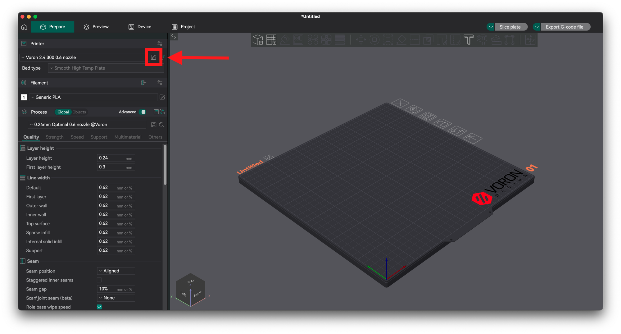
Navigate to Machine G-Code.
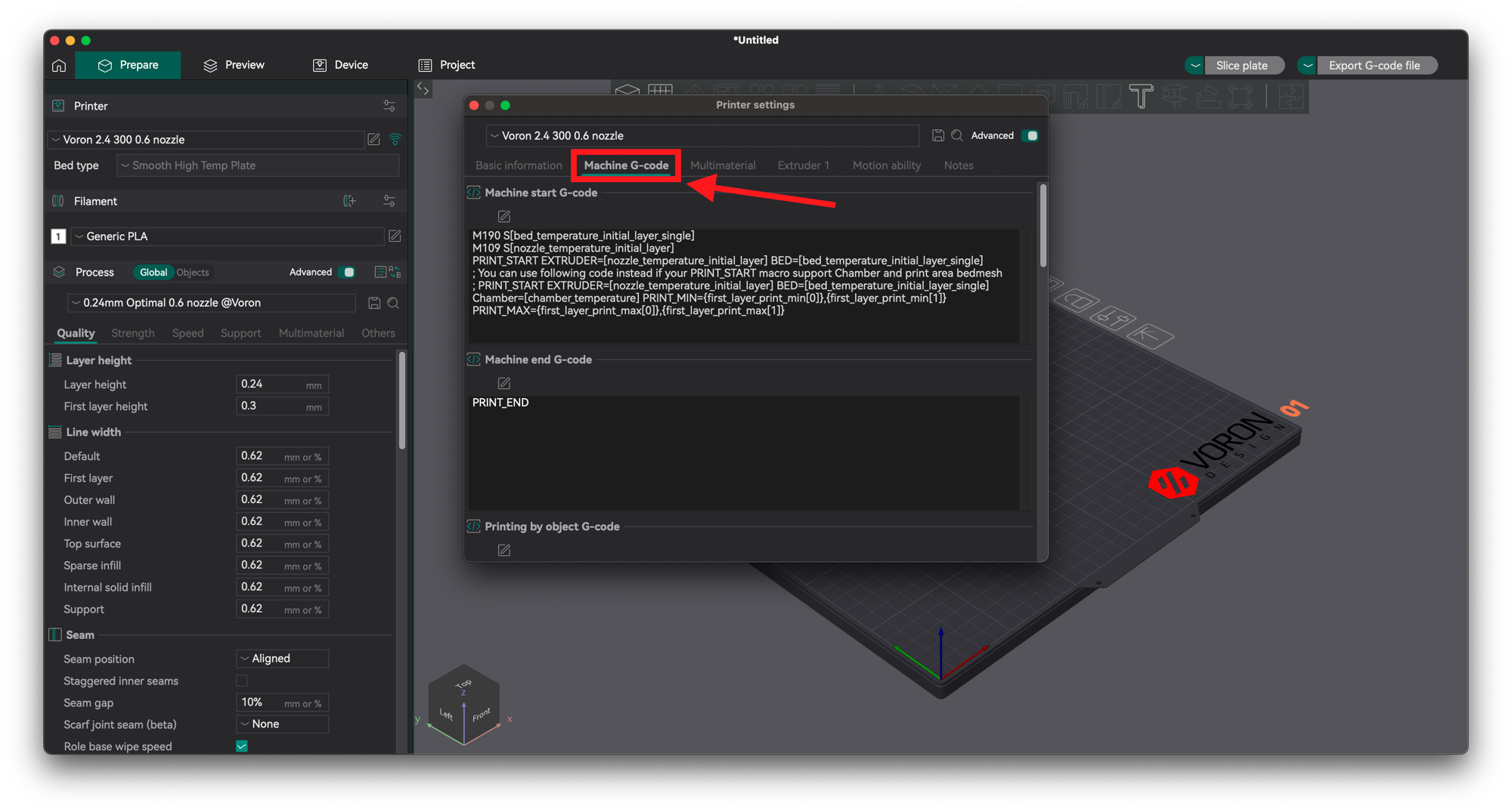
Start G-Code
Prepend your Machine start G-code with the following:
Then, append the following below your existing G-code:
End G-Code
Prepend your Machine end G-Code with the following:
Then, append the following below your existing G-code:
Layer Change G-Code
Scroll down and edit your layer change G-Code.
Add the following:
Save this machine preset with a new name.
Filament Settings
Filament Cutting vs. Tip Forming
It is recommended you install a filament cutter on your printer. This will make your toolchanges much more reliable and negate the tuning tip forming requires.
You can find user-submitted tip cutting/forming configurations here.
If you want to do tip forming and can't find the right configs for your setup at the above link, you will have to tune the values yourself. In general:
- Less cooling moves or higher temperature = stringy tips
- More cooling moves or lower temperature = blobby tips
- Skinnydip string reduction = less strings
Please upload your settings here once you tune yours in so other users can benefit!
Begin by opening your filament settings.
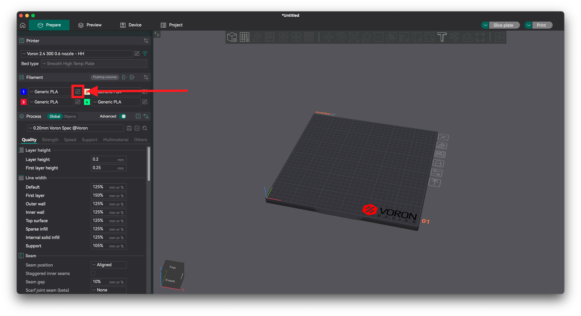
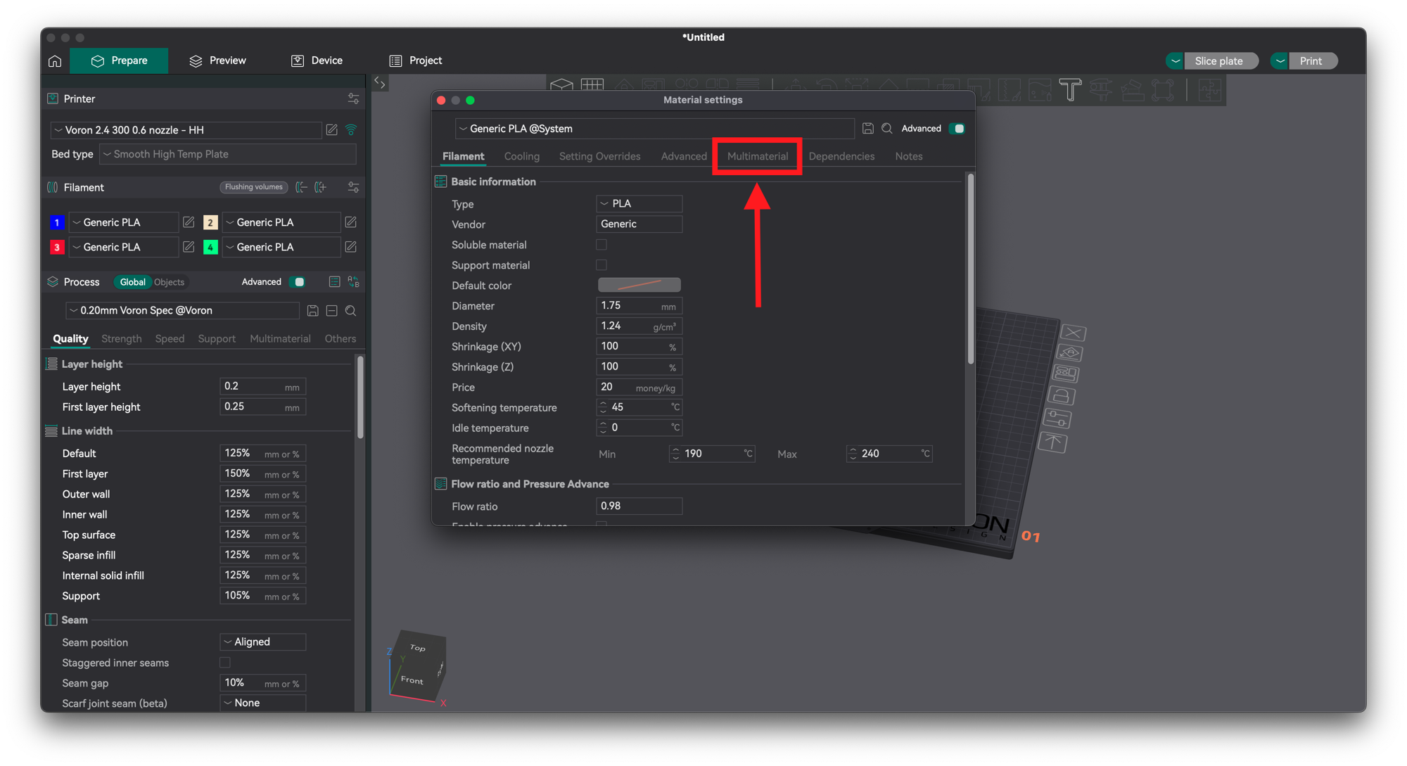
Navigate to Multimaterial.
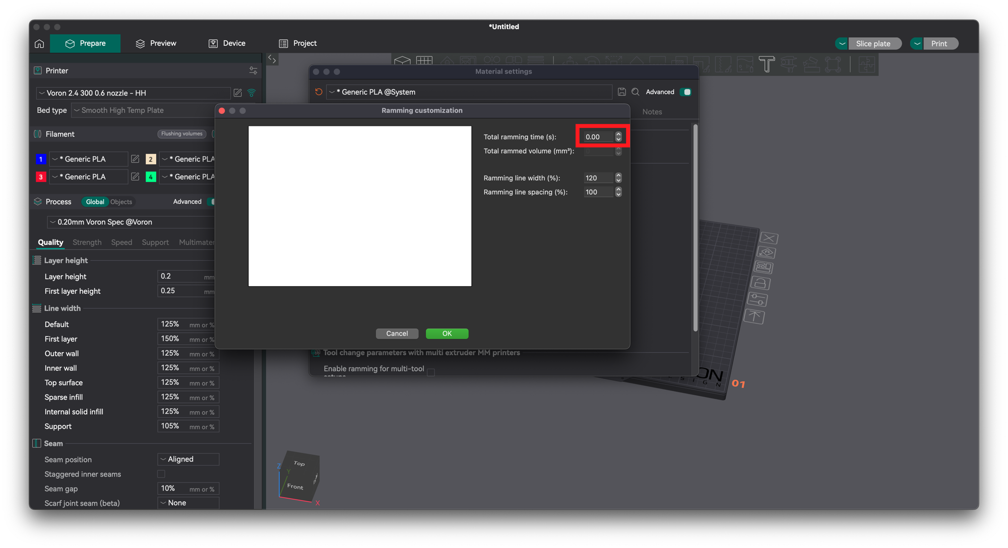
Disable Tip Forming
Set all the indicated fields to 0 and open the ramming settings.
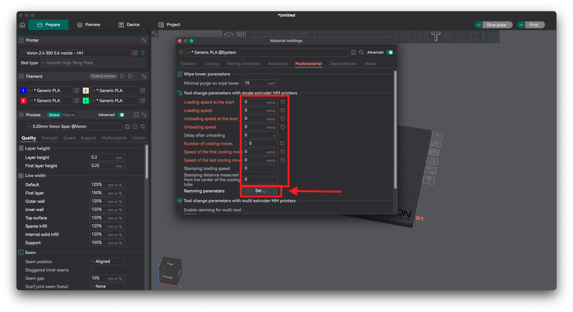
Set the ramming time to 0.
Your First Print
This section will cover one way to start multicolor 3D prints. Note that typically, multicolor 3D models will come pre-painted or in multiple parts, so the process will be slightly different.
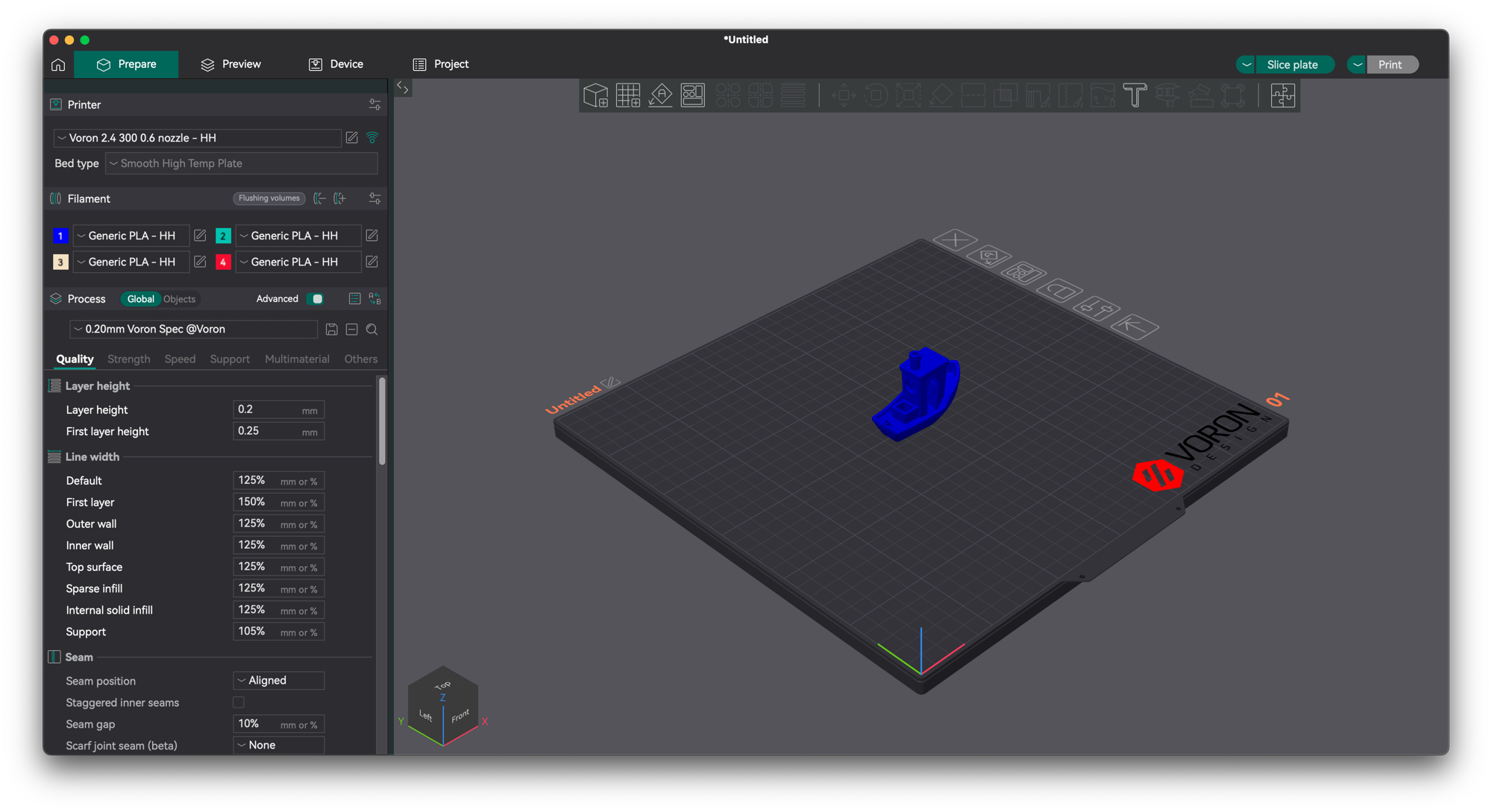
Begin by loading the model into the slicer.
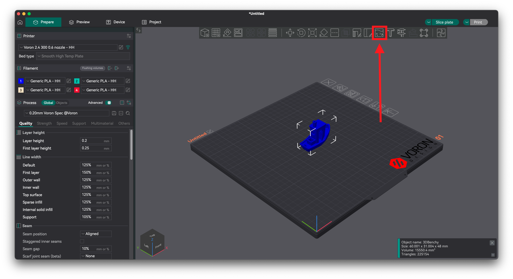
Select the model and click multicolor painting.
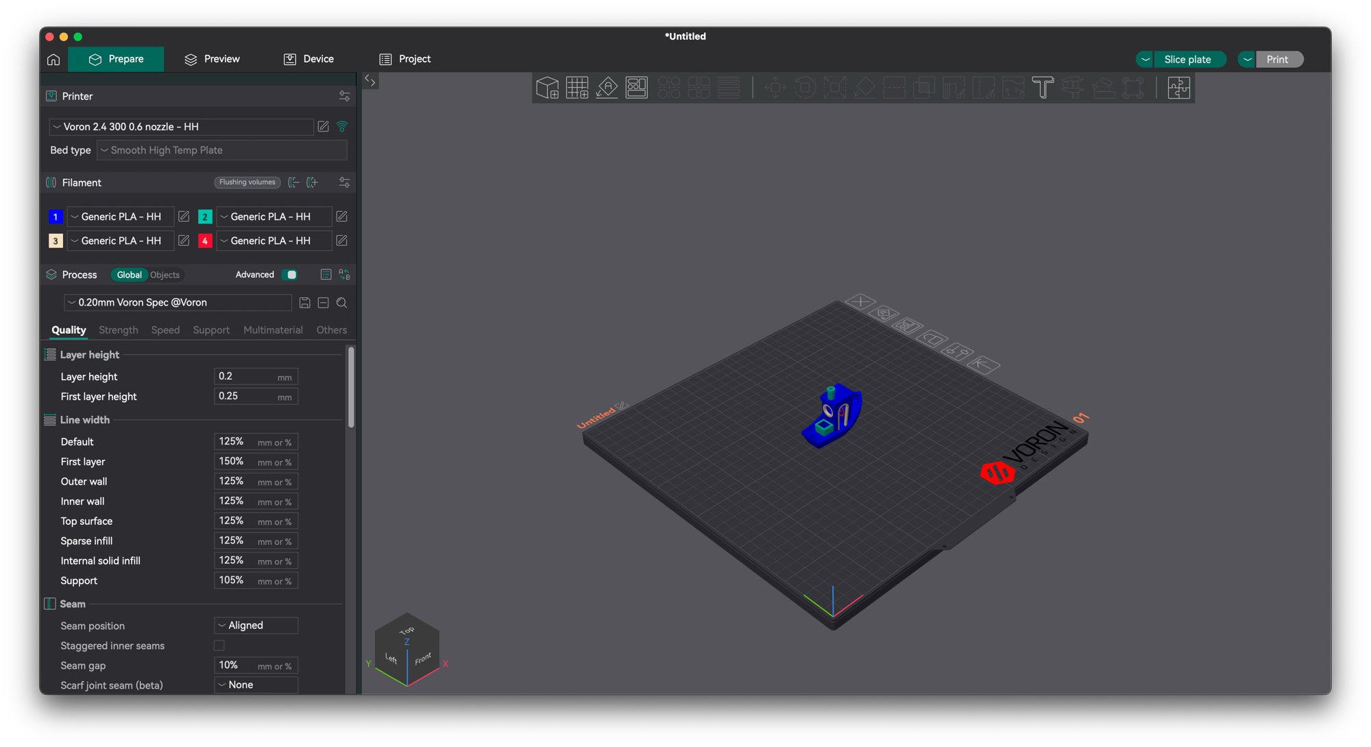
Paint the model as you like.
Ensure the prime tower is enabled.
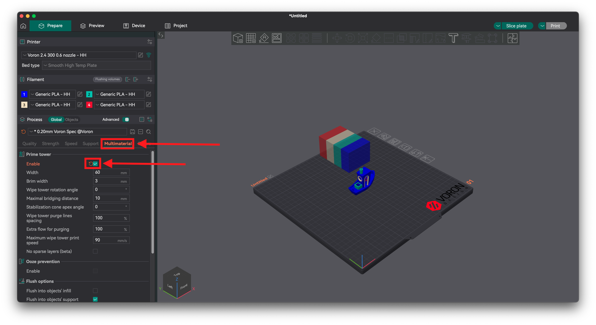
Arrange the prime tower on the plater.
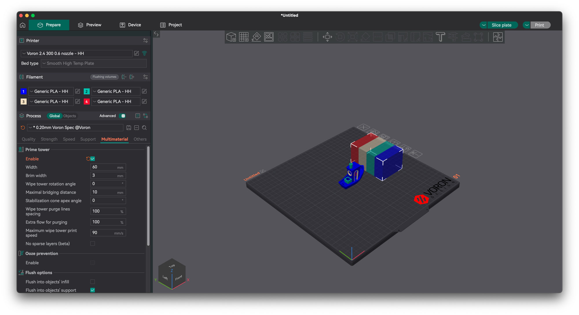
Slice and print!
I would really appreciate a star on GitHub if you enjoyed this project!
Other Boards
Kontrollboards
Folge diesem Guide um festzulegen welches Kontrollboard du in deinem 3MS verwenden kannst.
Optionen
Das 3MS funktioniert auf vielen verschiedenen Kontrollboards.
Info
Falls dein Drucker-Mainboard unbenutzte Stepper-Ports hat, kannst du diese verwenden um die Stepper des 3MS zu steuern. Du kannst einen Issue auf Github (es gibt eine Vorlage) erstellen um eine Config für dein spezifisches Setup zu erhalten. Alle controller mit "(main MCU)" nutzen solche freien Stepper-Ports.
Wähle einen der folgenden, unterstützten Controller (eine angekreuzte Box bedeutet, dass er vollständig getested ist, eine leere Box bedeutet, dass Tester gesucht werden):
-
Empfohlen
BTT SKR Pico
Firmware Installation
Setting up firmware for the SKR Pico can be divided into four major steps:
- Compile Katapult (bootloader)
- Flash Katapult
- Compile Klipper
- Flash Klipper
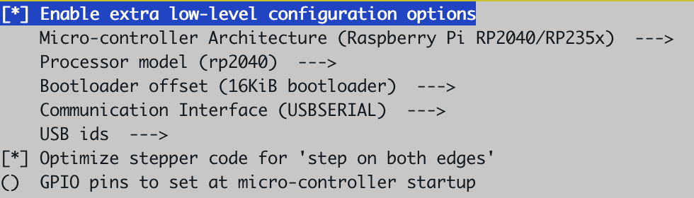
Compiling Katapult
You have two options for installing Katapult to the SKR Pico:
Run the following commands in SSH:
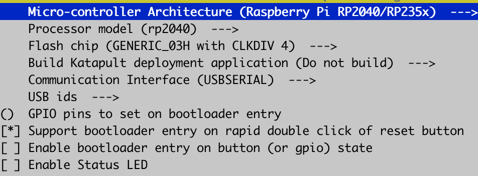
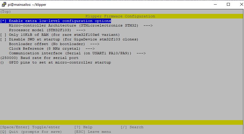
Adjust your menuconfig parameters to match the following exactly.
Then, run:
Now in Mainsail/Fluidd, download katapult.uf2 from your printer's config folder onto your computer and proceed to flashing.
Download katapult.uf2 to your computer and proceed to flashing.
Flashing Katapult
Now that you have katapult.uf2 on your computer, install the BOOT and VUSB jumpers onto the SKR Pico as shown in the below diagram.
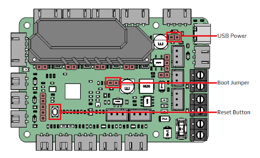
Credits: Voron Design
Plug the SKR Pico into your computer with the USB-C cable that came with it. It should show up as a USB drive.
Drag katapult.uf2 into the drive. It should quickly disconnect then reconnect itself.
Now, remove the BOOT jumper and unplug the Pico from your computer.
Compiling Klipper
Now, SSH into your Pi again and run the following commands:
Adjust your menuconfig settings to match this exactly:
Now, run:
Flashing Klipper
Run in SSH:
Plug the Pico into your Pi and double-click the RESET button.
There should be a new USB device shown after plugging the Pico in. Copy the entire path, including /dev/serial/by-id/, and run the final commands:
Your SKR Pico is now successfully flashed with Katapult and Klipper.
Kontrollboards
Folge diesem Guide um festzulegen welches Kontrollboard du in deinem 3MS verwenden kannst.
Optionen
Das 3MS funktioniert auf vielen verschiedenen Kontrollboards.
Info
Falls dein Drucker-Mainboard unbenutzte Stepper-Ports hat, kannst du diese verwenden um die Stepper des 3MS zu steuern. Du kannst einen Issue auf Github (es gibt eine Vorlage) erstellen um eine Config für dein spezifisches Setup zu erhalten. Alle controller mit "(main MCU)" nutzen solche freien Stepper-Ports.
Wähle einen der folgenden, unterstützten Controller (eine angekreuzte Box bedeutet, dass er vollständig getested ist, eine leere Box bedeutet, dass Tester gesucht werden):
-
Empfohlen
BTT MMB V1
Max filament units: 4
MCU Name: mmu
BOM
| Name | Price | Quantity | Link | Notes |
|---|---|---|---|---|
| BTT MMB | $34.99 | 1 | BTT | |
| 22AWG Cable | $9.99 | 1 | Amazon | These wires are only sufficient to run steppers, not heaters |
| 24V PSU | $7.39 | 1 | Amazon | This PSU is only sufficient to run steppers, not heaters |
For each filament unit, purchase the following:
| Name | Quantity | Price | Link | Notes |
|---|---|---|---|---|
| NEMA17 Stepper Motor | 1 | $9.99 | Amazon | You can use a pancake stepper if you want, but it will have less torque |
| BMG Clone Extruder | 1 | $9.99 | Amazon | Alternatively, you can use this Dual-drive MK8 based extruder |
| PTFE Tubing | 1 | $8.99 | Amazon | You likely won't need this for every unit, as this is usually too long for only one unit |
Wiring
Route the wires from the NEMA17's to the controller board. Follow this table to determine which port to plug the motors into:
| Filament Unit # | Motor Port |
|---|---|
| 0 | M1 |
| 1 | M2 |
| 2 | M3 |
| 3 | M4 |
Now, grab your 24V PSU and two M-M duponts, one red and one black (M-M means that there is metal coming out of both ends of the cable). Plug the PSU into the wall, but don't plug the screw terminals into the PSU (the screw terminals have green)
- Plug the red wire into the positive terminal of the screw terminals
-
Plug the black wire into the negative terminal of the screw terminals
Danger
These dupont cables are too thin to run much more than the stepper motors. If you run a heater or other power-intensive device off of the MMB board, the duponts and/or PSU can melt/catch fire. To reduce the risk of this, you can double up on the duponts or get thicker wires.
-
Following this image, locate the HVIN and GND inputs (top left)
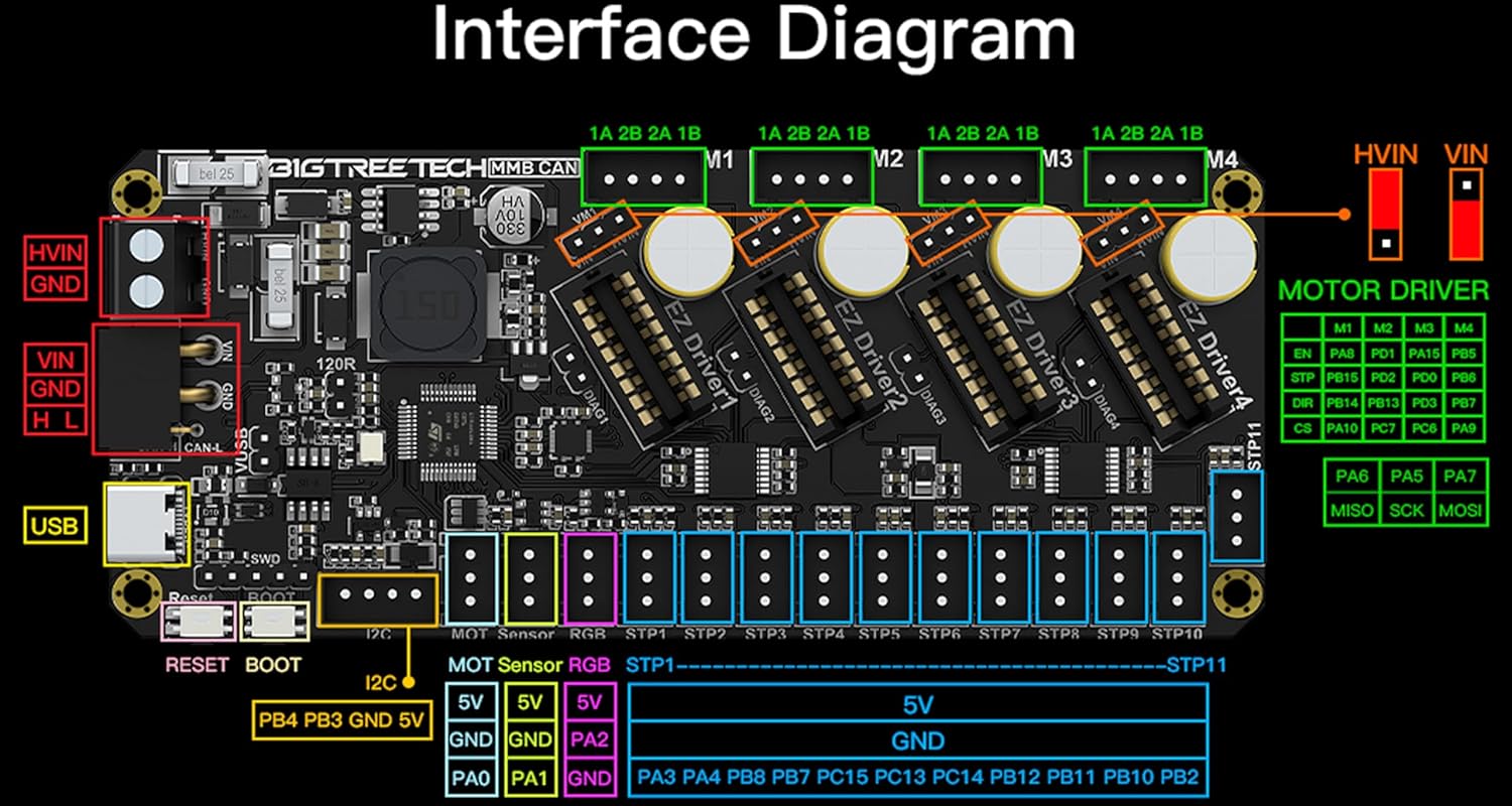
-
Route the two wires inside closest to the HVIN and GND inputs
- Using the markings on the board, plug the red wire into the HVIN terminal on the MMB
-
Using the markings on the board, plug the black wire into the GND terminal on the MMB
-
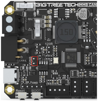
Install the VUSB jumper.
Tip
After you've flashed firmware, remove the VUSB jumper.
-
Verify all connections
Warning
If the wires are plugged into the wrong place, or swapped polarities, your MMB, Stepper motors, and/or PSU can be badly damaged.
-
Plug the PSU screw terminals into the PSU wire
Plug the MMB into your Klipper host with the cable that came with it.
If the MMB lights up, you wired it correctly!
BTT SKR Mini E3 V2
Max filament units: 4
MCU Name: 3ms
BOM
| Name | Price | Quantity | Link | Notes |
|---|---|---|---|---|
| SKR Mini E3 V2 | $34.99 | 1 | Amazon | |
| 22AWG Cables | $9.99 | 1 | Amazon | These wires are only sufficient to run steppers, not heaters |
| 12V PSU | $7.39 | 1 | Amazon | This PSU is only sufficient to run steppers, not heaters |
For each filament unit, purchase the following:
| Name | Quantity | Price | Link | Notes |
|---|---|---|---|---|
| NEMA17 Stepper Motor | 1 | $9.99 | Amazon | You can use a pancake stepper if you want, but it will have less torque |
| BMG Clone Extruder | 1 | $9.99 | Amazon | Alternatively, you can use this Dual-drive MK8 based extruder |
| PTFE Tubing | 1 | $8.99 | Amazon | You likely won't need this for every unit, as this is usually too long for only one unit |
Wiring
Route the wires from the NEMA17's to the controller board. Follow this table to determine which port to plug the motors into:
| Filament Unit # | Motor Port |
|---|---|
| 0 | XM |
| 1 | YM |
| 2 | ZAM or ZBM |
| 3 | E0M |
Now, grab your 12V PSU and two M-M duponts, one red and one black (M-M means that there is metal coming out of both ends of the cable). Plug the PSU into the wall, but don't plug the screw terminals into the PSU (the screw terminals have green)
- Plug the red wire into the positive terminal of the screw terminals
-
Plug the black wire into the negative terminal of the screw terminals
Danger
These dupont cables are too thin to run much more than the stepper motors. If you run a heater or other power-intensive device off of the SKR board, the duponts and/or PSU can melt/catch fire. To reduce the risk of this, you can double up on the duponts or get thicker wires.
-
Following this image, choose either the DCIN or POWER input
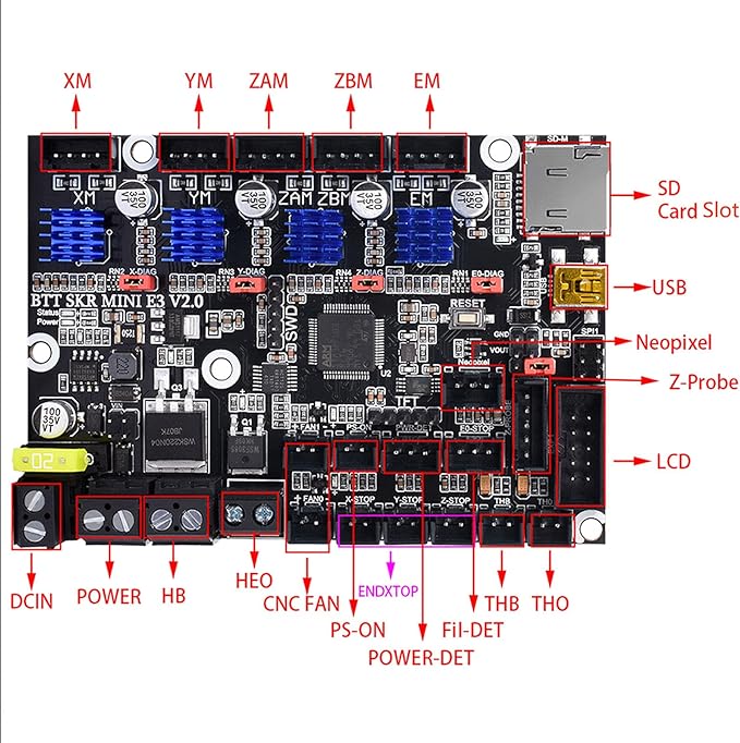
- Route the two wires inside closest to your chosen input
- Using the markings on the board, plug the red wire into the positive terminal on the SKR
- Using the markings on the board, plug the black wire into the negative terminal on the SKR
-
Verify all connections
Warning
If the wires are plugged into the wrong place, or swapped polarities, your SKR, Stepper motors, and/or PSU can be badly damaged.
-
Plug the PSU screw terminals into the PSU wire
If the SKR lights up, you wired it correctly!
Finally, plug the SKR into your Klipper host with the blue cable that came with it.
BTT Octopus (main MCU)
Warning
This configuration may not work with the BTT Octopus Pro.
Max filament units: 4
MCU Name: main
main MCU
This configuration is a main MCU configuration, meaning that your printer should already be running off a BTT Octopus and you don't need to purchase one.
BOM
Per filament unit:
1x TMC2209 ($7 each)
For each filament unit, purchase the following:
| Name | Quantity | Price | Link | Notes |
|---|---|---|---|---|
| NEMA17 Stepper Motor | 1 | $9.99 | Amazon | You can use a pancake stepper if you want, but it will have less torque |
| BMG Clone Extruder | 1 | $9.99 | Amazon | Alternatively, you can use this Dual-drive MK8 based extruder |
| PTFE Tubing | 1 | $8.99 | Amazon | You likely won't need this for every unit, as this is usually too long for only one unit |
Wiring
Route the wires from the NEMA17's to the controller board. Follow this table to determine which port to plug the motors into:
| Filament Unit # | Motor Port |
|---|---|
| 0 | MOTOR7 |
| 1 | MOTOR6 |
| 2 | MOTOR5 |
| 3 | MOTOR4 |
Einsy RAMBo (main MCU) with SKR Mini E3 V2
Danger
This guide is an expert guide only
Info
This modification is designed for the Prusa MK3/S/S+, and depends on this Klipper configuration.
Why?
When printing fast, the TMC2130's on the Einsy RAMBo can get quite loud. The TMC2209's on the SKR Mini are much quieter and support denser microstepping.
BOM
| Name | Price | Quantity | Link | Notes |
|---|---|---|---|---|
| PSU -> Einsy Cable | $7.99 | 1 | PartsBuilt3D | |
| Stepperonline NEMA17 | $9.99 each | Amazon | 2 | Replaces current XY motors |
For each filament unit, purchase the following:
| Name | Quantity | Price | Link | Notes |
|---|---|---|---|---|
| NEMA17 Stepper Motor | 1 | $9.99 | Amazon | You can use a pancake stepper if you want, but it will have less torque |
| BMG Clone Extruder | 1 | $9.99 | Amazon | Alternatively, you can use this Dual-drive MK8 based extruder |
| PTFE Tubing | 1 | $8.99 | Amazon | You likely won't need this for every unit, as this is usually too long for only one unit |
Wiring
First, unplug the 3MS steppers from the SKR Mini, and the XY steppers from the Einsy RAMBo. The motors will need to be switched due to different connector types between boards.
This table outlines the major wiring of this modification.
| Einsy RAMBo | SKR Mini E3 V2 | Motor |
|---|---|---|
| PSU+ | POWER+ | |
| PSU- | POWER- | |
| XM | 3ms0 | |
| YM | 3ms1 | |
| XM | X | |
| YM | Y |
Configuration
In your printer.cfg, comment out these lines:
| printer.cfg | |
|---|---|
Next, copy the contents of 3ms/controllers/einsy_rambo_with_skr_mini/xy-motors.cfg and ze-motors.cfg to klipper-prusa-mk3s/skr/xy.cfg, and klipper-prusa-mk3s/mk3s/ze.cfg, respectively.
Add the following new lines:
Restart Klipper.
Zonestar ZM384 (main MCU)
Max filament units: 3
MCU Name: main
main MCU
This configuration is a main MCU configuration, meaning that your printer should already be running off a ZM384 and you don't need to purchase one.
For each filament unit, purchase the following:
| Name | Quantity | Price | Link | Notes |
|---|---|---|---|---|
| NEMA17 Stepper Motor | 1 | $9.99 | Amazon | You can use a pancake stepper if you want, but it will have less torque |
| BMG Clone Extruder | 1 | $9.99 | Amazon | Alternatively, you can use this Dual-drive MK8 based extruder |
| PTFE Tubing | 1 | $8.99 | Amazon | You likely won't need this for every unit, as this is usually too long for only one unit |
| Filament Unit # | Motor Port |
|---|---|
| 0 | E0 |
| 1 | E1 |
| 2 | E2 |
| 3 | E3 |
Mini RAMBo
Max filament units: 4
MCU Name: 3ms
BOM
| Name | Price | Quantity | Link | Notes |
|---|---|---|---|---|
| Mini RAMBo | 1 | |||
| 22AWG Cables | $9.99 | 1 | Amazon | These wires are only sufficient to run steppers, not heaters |
| 12V PSU | $7.39 | 1 | Amazon | This PSU is only sufficient to run steppers, not heaters |
For each filament unit, purchase the following:
| Name | Quantity | Price | Link | Notes |
|---|---|---|---|---|
| NEMA17 Stepper Motor | 1 | $9.99 | Amazon | You can use a pancake stepper if you want, but it will have less torque |
| BMG Clone Extruder | 1 | $9.99 | Amazon | Alternatively, you can use this Dual-drive MK8 based extruder |
| PTFE Tubing | 1 | $8.99 | Amazon | You likely won't need this for every unit, as this is usually too long for only one unit |
Wiring
Route the wires from the NEMA17's to the controller board. Follow this table to determine which port to plug the motors into:
| Filament Unit # | Motor Port |
|---|---|
| 0 | XM |
| 1 | YM |
| 2 | ZAM or ZBM |
| 3 | E0M |
Now, grab your 12V PSU and two M-M duponts, one red and one black (M-M means that there is metal coming out of both ends of the cable). Plug the PSU into the wall, but don't plug the screw terminals into the PSU (the screw terminals have green)
- Plug the red wire into the positive terminal of the screw terminals
-
Plug the black wire into the negative terminal of the screw terminals
Danger
These dupont cables are too thin to run much more than the stepper motors. If you run a heater or other power-intensive device off of the RAMBo board, the duponts and/or PSU can melt/catch fire. To reduce the risk of this, you can double up on the duponts or get thicker wires.
-
Route the two wires inside closest to your chosen input
- Using the markings on the board, plug the red wire into the positive terminal on the RAMBo
- Using the markings on the board, plug the black wire into the negative terminal on the RAMBo
-
Verify all connections
Warning
If the wires are plugged into the wrong place, or swapped polarities, your RAMBo, Stepper motors, and/or PSU can be badly damaged.
-
Plug the PSU screw terminals into the PSU wire
If the RAMBo lights up, you wired it correctly!
Finally, plug the RAMBo into your Klipper host with the cable that came with it.
Mellow Fly D7
Max filament units: 7
MCU Name: 3ms
BOM
| Name | Price | Quantity | Link | Notes |
|---|---|---|---|---|
| Mellow Fly D7 | 1 | |||
| 22AWG Cables | $9.99 | 1 | Amazon | These wires are only sufficient to run steppers, not heaters |
| 12V PSU | $7.39 | 1 | Amazon | This PSU is only sufficient to run steppers, not heaters |
For each filament unit, purchase the following:
| Name | Quantity | Price | Link | Notes |
|---|---|---|---|---|
| NEMA17 Stepper Motor | 1 | $9.99 | Amazon | You can use a pancake stepper if you want, but it will have less torque |
| BMG Clone Extruder | 1 | $9.99 | Amazon | Alternatively, you can use this Dual-drive MK8 based extruder |
| PTFE Tubing | 1 | $8.99 | Amazon | You likely won't need this for every unit, as this is usually too long for only one unit |
Wiring
Route the wires from the NEMA17's to the controller board. Follow this table to determine which port to plug the motors into:
| Filament Unit # | Motor Port |
|---|---|
| 0 | X |
| 1 | Y |
| 2 | Z |
| 3 | Z1 |
| 4 | Z2 |
| 5 | E0 |
Now, grab your 12V PSU and two M-M duponts, one red and one black (M-M means that there is metal coming out of both ends of the cable). Plug the PSU into the wall, but don't plug the screw terminals into the PSU (the screw terminals have green)
- Plug the red wire into the positive terminal of the screw terminals
-
Plug the black wire into the negative terminal of the screw terminals
Danger
These dupont cables are too thin to run much more than the stepper motors. If you run a heater or other power-intensive device off of the board board, the duponts and/or PSU can melt/catch fire. To reduce the risk of this, you can double up on the duponts or get thicker wires.
-
Using the markings on the board, plug the red wire into the positive terminal on the board
- Using the markings on the board, plug the black wire into the negative terminal on the board
-
Verify all connections
Warning
If the wires are plugged into the wrong place, or swapped polarities, your board, Stepper motors, and/or PSU can be badly damaged.
-
Plug the PSU screw terminals into the PSU wire
If the board lights up, you wired it correctly!
Finally, plug the board into your Klipper host with the cable that came with it.
Geetech A30T
Contributed by @ImChrono
Max filament units: 7
MCU Name: 3ms
BOM
| Name | Price | Quantity | Link | Notes |
|---|---|---|---|---|
| Geetech A30T | $34.99 | 1 | Geetech | |
| 22AWG Cables | $9.99 | 1 | Amazon | These wires are only sufficient to run steppers, not heaters |
| 24V PSU | $7.39 | 1 | Amazon | This PSU is only sufficient to run steppers, not heaters |
For each filament unit, purchase the following:
| Name | Quantity | Price | Link | Notes |
|---|---|---|---|---|
| NEMA17 Stepper Motor | 1 | $9.99 | Amazon | You can use a pancake stepper if you want, but it will have less torque |
| BMG Clone Extruder | 1 | $9.99 | Amazon | Alternatively, you can use this Dual-drive MK8 based extruder |
| PTFE Tubing | 1 | $8.99 | Amazon | You likely won't need this for every unit, as this is usually too long for only one unit |
Firmware
To flash Klipper firmware to the A30T, run the following command and see the following screenshot:
Next, connect the BOOT0 jumper on the A30T and run:
Wiring
Route the wires from the NEMA17's to the controller board. Follow this table to determine which port to plug the motors into:
| Filament Unit # | Motor Port |
|---|---|
| 0 | X |
| 1 | Y |
| 2 | Z0 |
| 3 | Z1 |
| 4 | E1 |
| 5 | E2 |
| 6 | E3 |
Now, grab your 12V PSU and two M-M duponts, one red and one black (M-M means that there is metal coming out of both ends of the cable). Plug the PSU into the wall, but don't plug the screw terminals into the PSU (the screw terminals have green)
- Plug two red wires into the positive terminal of the screw terminals
-
Plug two black wires into the negative terminal of the screw terminals
Danger
These dupont cables are too thin to run much more than the stepper motors. If you run a heater or other power-intensive device off of the motherboard, the duponts and/or PSU can melt/catch fire. To reduce the risk of this, you can double up on the duponts or get thicker wires.
-
Route the four wires inside closest to your chosen input
- Using the markings on the board, plug the two red wires into the positive terminal on the motherboard
- Using the markings on the board, plug the two black wires into the negative terminal on the motherboard
-
Verify all connections
Warning
If the wires are plugged into the wrong place, or swapped polarities, your motherboard, Stepper motors, and/or PSU can be badly damaged.
-
Plug the PSU screw terminals into the PSU wire
If the motherboard lights up, you wired it correctly!
Finally, plug the motherboard into your Klipper host with the cable that came with it.
UART Conversion
⚠️ Attention: Proceed with Caution! ⚠️
This modification involves delicate hardware changes that require precision and attention to detail. Mistakes in wiring or soldering can permanently damage your GTM32_103_V1 board.
- Double-check connections before applying power.
- Use proper tools and follow best practices for soldering.
- If you are not confident in your skills, seek assistance from an experienced individual or professional.
You proceed at your own risk.
Overview
This guide details the process of modifying the GTM32_103_V1 3D printer controller board to enable UART capabilities. The GTM32_103_V1 board features 7 TMC2208 drivers operating in standalone mode by default. This modification involves removing the SD card slot and repurposing its pinouts for UART communication.
Features of the Modification
- UART Capability: Enables communication with TMC2208 drivers via UART repurposing the SDCard slot
Hardware Changes
Components Modified
- SD Card Slot: Removed entirely to free up pinouts for UART.
- Repurposed Pins: SD card slot pins are reassigned as per the following table:
| TCM2208 Driver | SD Card Pin | STM32 Pin |
|---|---|---|
| Motor0 | 9 | PC7 |
| Motor1 | 8 | PC9 |
| Motor2 | 7 | PC8 |
| Motor3 | 5 | PC12 |
| Motor4 | 3 | PD2 |
| Motor5 | 2 | PC11 |
| Motor6 | 1 | PC10 |
Procedure
- Remove Pull down resistor from each driver:
- Desolder the SMD 1kΩ resistor carefully to avoid damaging the surrounding components.
| TMCDriver | PCB Code |
|---|---|
| Motor0 | R53 |
| Motor1 | R57 |
| Motor2 | R62 |
| Motor3 | R120 |
| Motor4 | R71 |
| Motor5 | R95 |
| Motor6 | R105 |
- Remove the SD Card Slot:
- Desolder the SD card slot carefully to avoid damaging the surrounding components.
- Repurpose the Pinouts:
- Rewire the SD card pins according to the table above.
- Connect each pin to its corresponding UART connection for the TMC2208 drivers.
Testing and Validation
After completing the hardware changes: 1. Connect the board to your 3D printer and power it on. 2. Use your firmware to verify UART communication with each TMC2208 driver. 3. Check for successful responses from the drivers using a terminal or debugging tool.
Photos
Add your photos here to demonstrate the modification process and results:
- Close-up of the TMC driver
-Close-up of the TMC driver with resistor removed (solder the uart pint to the red signed pin)
-
Close-up of the SD card:
-
Rewired pins with labels.
UART Configuration
When configuring this board with Happy Hare firmware, be sure to use UART-mmu.cfg and UART-mmu_hardware.cfg (renaming to mmu.cfg and mmu_hardware.cfg respectively).
Kits
3MS Kits

Disclaimer
By using the 3MS, you agree to the terms outlined in the full disclaimer and accept full responsibility for its assembly and use. The creators are not liable for any damage, loss, or harm caused by the product.
Full Disclaimer
Full Disclaimer
The 3MS (Modular MultiMaterial System) is provided as-is, with no guarantees or warranties, expressed or implied, regarding its performance, safety, reliability, or suitability for any particular purpose. By purchasing, assembling, or using the 3MS, you acknowledge and agree to the following terms and conditions:
-
Assumption of Risk The use, assembly, and operation of the 3MS are entirely at your own risk. You are solely responsible for ensuring the proper assembly, configuration, and operation of the product. The creators, contributors, and distributors of the 3MS are not liable for any damage, including but not limited to:
- Damage to your 3D printer, components, or other equipment.
- Property damage resulting from use or misuse.
- Personal injury, including but not limited to burns, cuts, or other physical harm.
-
No Warranties or Guarantees The 3MS is sold as a consumer-ready product designed for hobbyist use but is not guaranteed to function without issue in all environments or scenarios. While the instructions provided aim to ensure a successful assembly and operation, they may not account for every possible issue, user error, or unique configuration. No warranties, express or implied, including but not limited to fitness for a particular purpose, are provided.
-
Responsibility for Assembly and Use Assembly of the 3MS requires basic technical skills, including mechanical assembly and firmware configuration. It is your responsibility to carefully follow the instructions and ensure all components are installed and configured correctly. Failure to do so may result in malfunction, damage, or injury, for which the creators, contributors, and distributors are not responsible.
-
Compatibility and Modifications The 3MS is designed to be compatible with a variety of 3D printers, but compatibility is not guaranteed in all cases. Modifications to the hardware, firmware, or system setup may lead to unintended consequences, and the creators and distributors are not responsible for any resulting issues.
-
Void of Warranty Use of the 3MS may void the warranty of your 3D printer and other components. The creators, contributors, and distributors are not liable for any issues related to warranty claims or repairs resulting from the use of the 3MS.
-
Indemnification By using the 3MS, you agree to indemnify and hold harmless the creators, contributors, and distributors from any claims, damages, or liabilities arising from your use of the product, including but not limited to damages to personal property, injury, or harm caused by incorrect assembly, configuration, or operation.
-
Limitation of Liability Under no circumstances will the creators, contributors, or distributors be liable for any indirect, incidental, special, or consequential damages arising from the use or inability to use the 3MS, including but not limited to loss of profits, data, or business opportunities, even if advised of the possibility of such damages.
By purchasing or using the 3MS, you agree to the terms outlined in this disclaimer and release the creators, contributors, and distributors from any claims or liabilities arising from its use. If you do not agree to these terms, do not proceed with assembly or use of the 3MS.
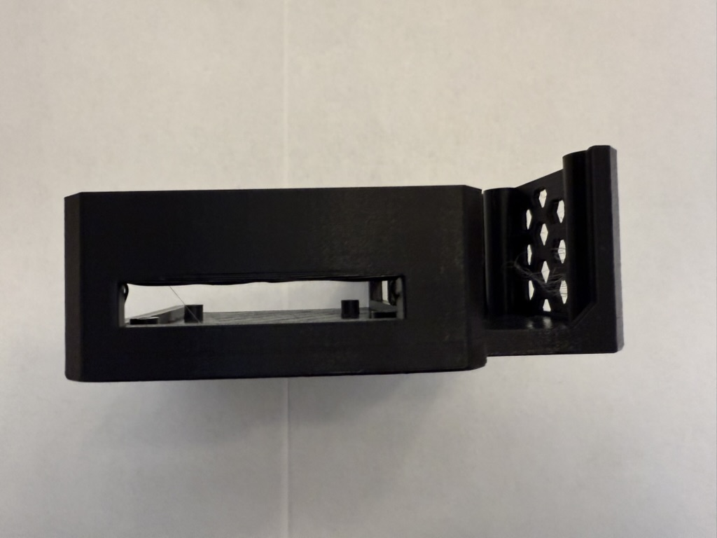
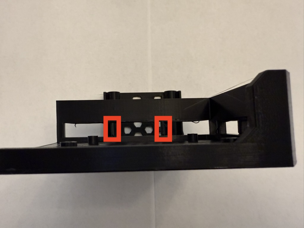
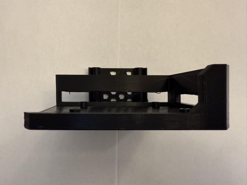
Tour
For a detailed look at what's included in 3MS kits, check out this tour below:
Instructions
To assemble and set up your 3MS kit, follow the instructions below.
Survey
I'd really appreciate it if you could take a couple minutes and fill out this quick survey about your experience with the kit.
3MS Kits: A First Look
After several months of planning and preparation, I am super excited to release this first look for 3MS kits.
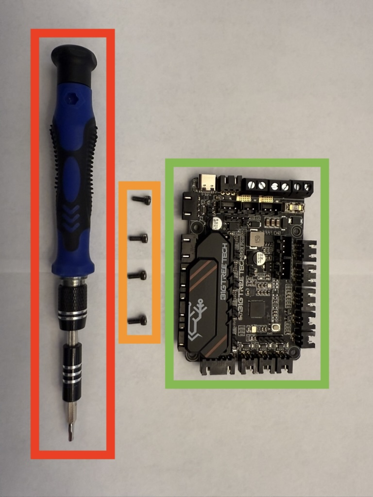
What's inside
3MS kits include:
-
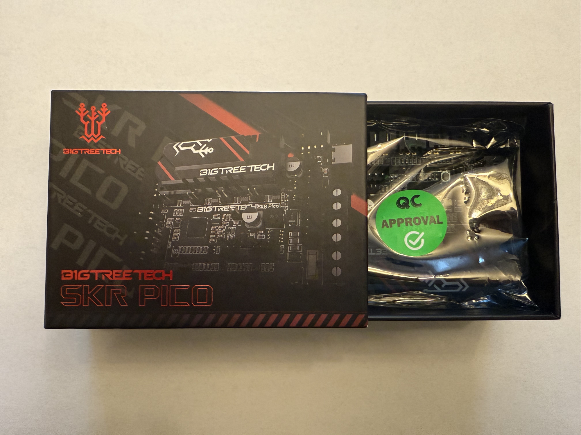
BTT SKR Pico board
Each board is pre-flashed with the latest Klipper firmware and checked for MCU functionality.
-
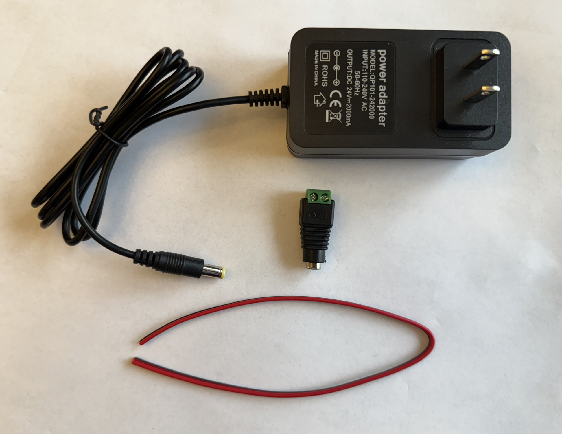
Power Supply
Each kit includes a PSU rated for 24V@2A, ~10in of black and red power cables, and an adapter to a screw terminal.
-
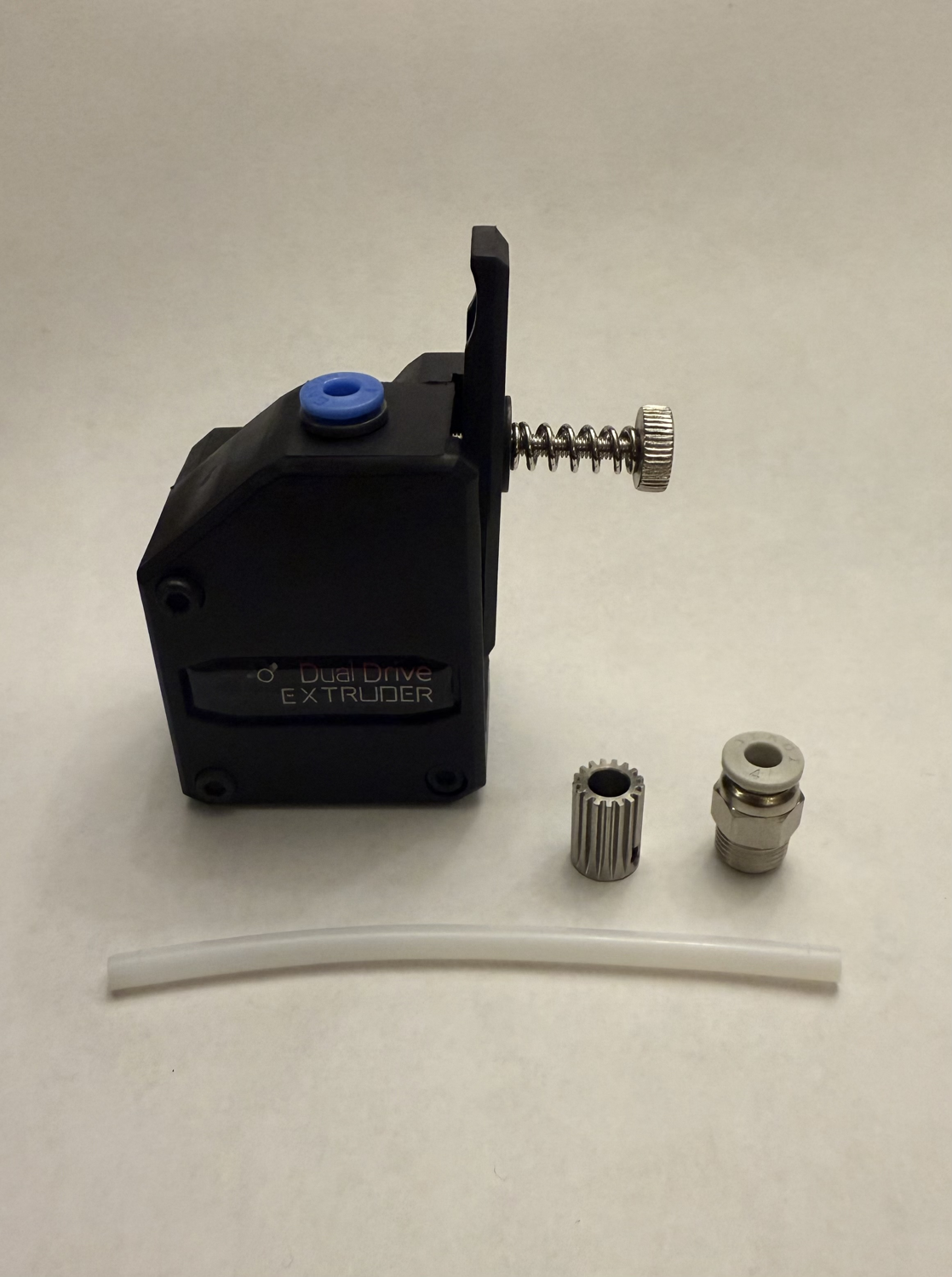
Extruders
Each kit includes four BMG-style extruders to drive the filament.
-
Stepper Motors
Each kit includes four NEMA17 stepper motors to drive the extruders.
-
PTFE Tubing
Each kit includes 10ft of 2mmIDx4mmOD PTFE tubing, five PC4-M10 fittings, and five ECAS04 fittings so you can use any Y-splitter.
-
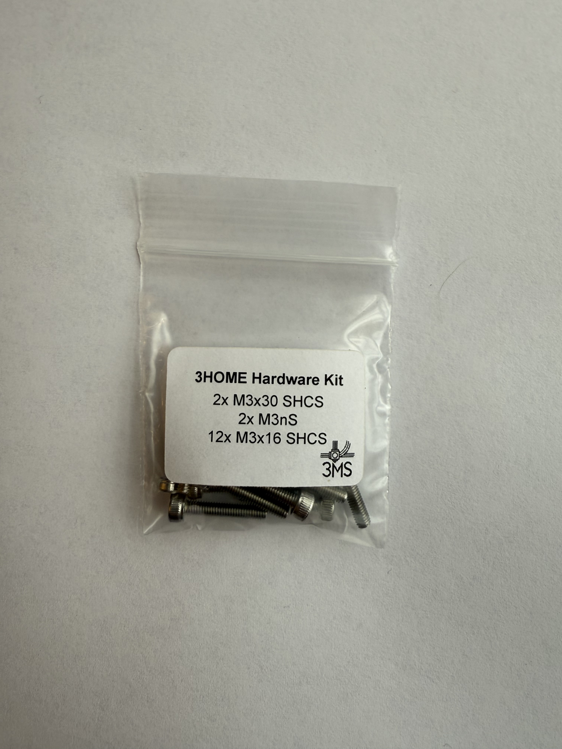
3HOME Fasteners Kit
Each kit includes the necessary fasteners to build a 3HOME, the official modular enclosure for the 3MS.
Includes
- 1x BTT SKR Pico board
- 1x PSU
- 1x PSU to screw terminal adapter
- 1x Power cables (black and red)
- 4x NEMA17 stepper motor
- 4x BMG-style extruder
- 1x PTFE tubing (10ft)
- 5x PC4-M10 bowden fittings
- 5x ECAS04 bowden fittings
- 1x 3HOME fasteners kit
Guides
Printers
Creality E3v3 series
Introduction
The Creality K1 Ender 3 v3 series printers run a heavily modified Klipper and Linux installation. Because of this, setup isn't as straightforward as on a genuine Klipper and Linux install. If you have another printer running mainline Klipper, it is highly recommended to install the 3MS on it instead.
If you would like to use the 3MS on an E3v3, read on.
Tip
Please read every step here carefully. If you run into issues, please reach out on the 3MS Discord (link on homepage) and note the step you are having trouble with.
Disclaimer
I am not responsible for whatever happens to your machine! You proceed at your own risk and understand that you will likely void your warranty by proceeding.
Instructions
Thank you @dr-evil-23 for figuring this out!
-
Compile and flash Katapult to your board.
If you're using an SKR Pico, select
W25Q080 with CLKDIV 2as the flash chip. -
Compile Klipper v0.12.0 and flash to your board.
You can follow the rest of the documentation as usual from here.
Config-Generator
Folge diesem Guide um eine Custom-Config für dein 3MS zu generieren.
Grundlagen-Config
Als erstes musst du eine Klipper-Config für dein Mainboard finden. Der beste Ort um diese zu finden sind die official Klipper sample configurations.
In diesem Beispiel wird ein BTT SKR Mini E3 V3 verwendet. Eine Grundlagen-Config ist hier verfügbar.
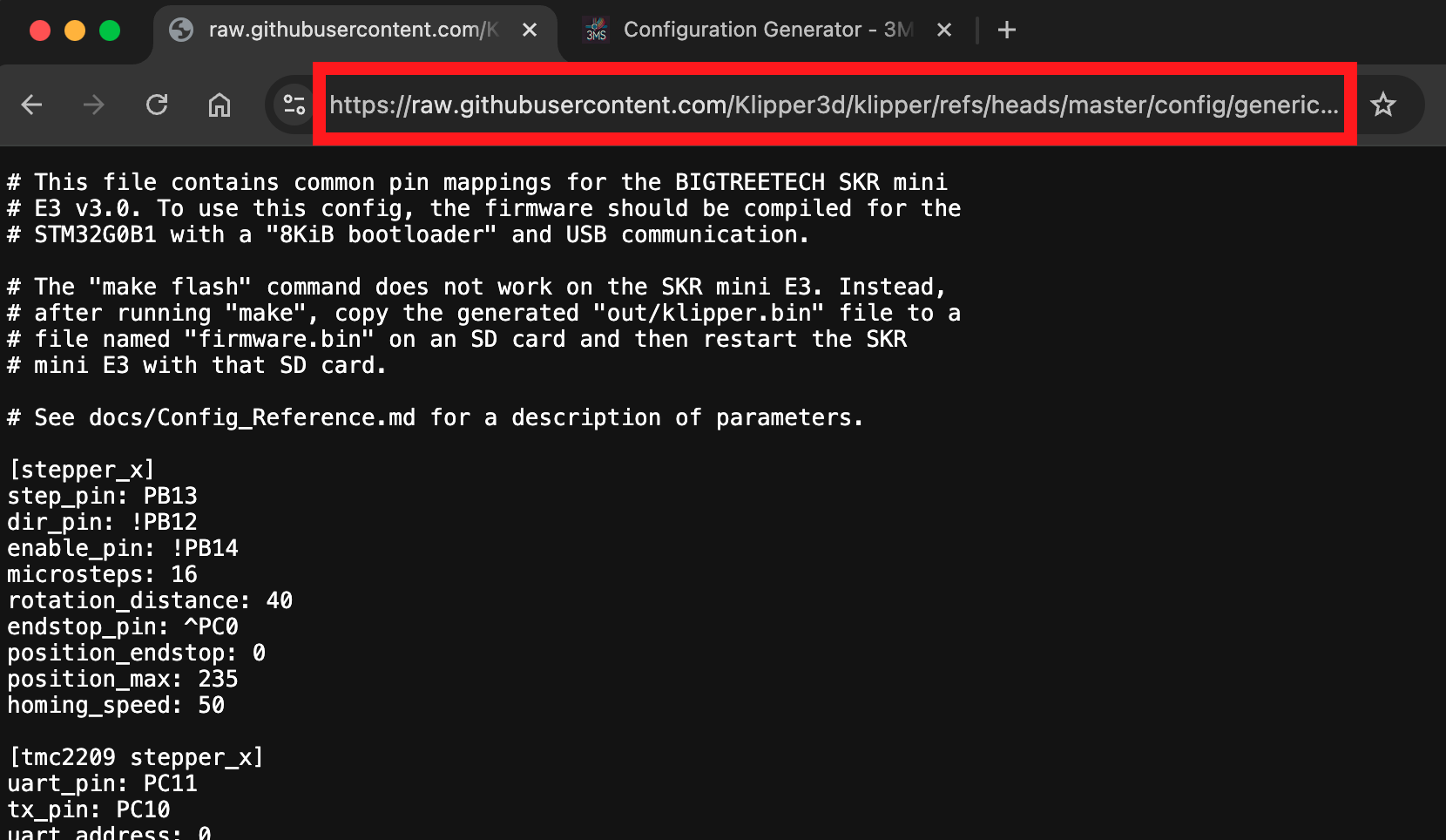
Rohdatei
Jetzt hast du die Config, aber sie ist keine Rohdatei, sondern eine volle Website. Um Fortzufahren brauchst du die Rohdatei. Um sie zu erhalten musst du auf den "Raw" Button in Ecke Oben-Rechts klicken.
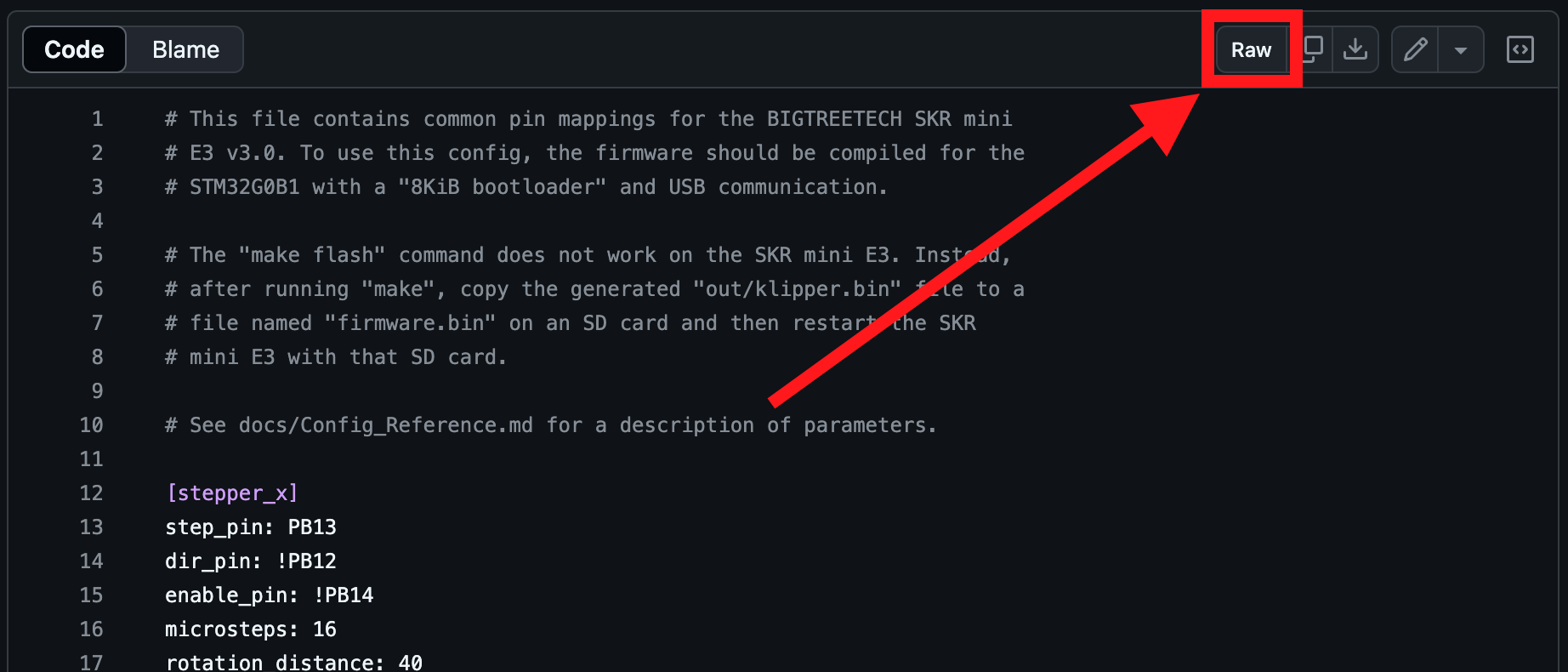
Jetzt wirst du auf eine Seite mit der Rohdatei weitergeleitet. Kopiere die URL aus der Addresszeile.
Generieren der Config - Web
ODER
Generieren der Config - Shell
Jetzt wo du die URL der Rohdatei hast, musst du das Generatorskript installieren.
Installation
-
Klone das 3MS repository:
-
Stelle sicher dass Python 3 installiert ist (nicht Python 2).
-
Installiere
requests
Das Skript ausführen
Starte als erstes das Skript:
Jetzt werden dir verschiedene Optionen angezeigt.
Config URL
Füge die vorhin erhaltene URL ein.
Lokale Datei verwenden
Du kannst auch eine lokale Config-Datei verwenden, indem du den --file Parameter übergibst.

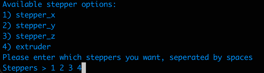
Ausgewählte Stepper
Das Skript wird dir nun alle Stepper Definitionen, die in der Config gefunden wurden, jeweils mit einer Nummer, auflisten. Gebe die gewünschten Stepper, mit Leerzeichen getrennt, ein.
TMC Treiber
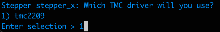
Für jeden von dir ausgewählten Stepper wird das Skript dich fragen, welchen TMC Treiber du verwenden möchtest. Für den SKR Mini E3 V3 gibt es nur eine Option: TMC2209.
Keine TMC Treiber?
Wenn du keine TMC-Treiber in deiner Config verwenden willst, übergebe den Parameter --no-tmc:
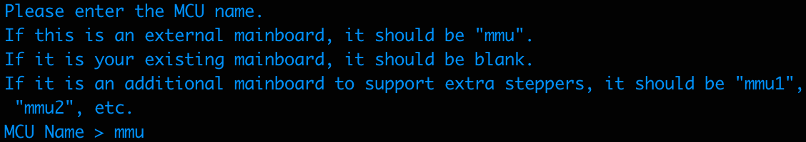
MCU Name
Schließlich fragt das Skript dich nach dem Namen der MCU, die dein 3MS steuert. Folge der Namenskonvention, die in der Prompt angegeben ist.
Deine Konfiguration wird nun in ~/3MS/mmu.cfg und ~/3MS/mmu_hardware.cfg verfügbar sein.
Tuning Stepper Current
Tuning stepper current is an important part of any 3D printer, including MMU's. Follow this guide to find the optimal run_current setting for your 3MS gear steppers.
Why Tune Stepper Current?
Firstly, why tune stepper current in the first place?
If your stepper current is too low, you might notice your stepper skipping when trying to move filament.
If your stepper current is too high, you might notice your stepper grinding filament if something is preventing its motion.
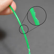
Grinding filament
Source: Simplify3D
Follow the below steps to tune your 3MS gear steppers.
Hardware Limits
Firstly, find the maximum current your stepper can safely run at. There are three main things that can limit this. For this example, components from 3MS Kits will be used.
- PSU rated current. The PSU included in 3MS kits is rated to 2A. The stepper current cannot exceed this.
- Driver rated current. The TMC2209's on the SKR Pico included in 3MS kits are rated to 2A continuous current. The stepper current cannot exceed this.
- Stepper rated current. The steppers included in 3MS kits are rated to 1A. Generally, you don't want to exceed 75% of your stepper's rated current, bringing down our safe limit to 0.75A. The stepper current cannot exceed this.
The lowest of the three values (for this example) is 0.75A. Therefore, your run_current cannot exceed 0.75A of current.
Maximum Current
Now that the maximum safe current for the steppers is known, we can test the stepper at the max current to see if it can drive filament at its max current.
First, set your run_current to the maximum calculated previously.
Restart Klipper.
There are two parts to this test:
- Free filament test
- Blocked filament test
Free Filament Test
Begin by detaching the PTFE from the exit of the 3MS extruder and manually loading filament into the extruder. Next, run in your Mainsail/Fluidd console:
Operation not possible. MMU has filament loaded
1 2 3 4 5 | |
Observe the behavior of the stepper. If your stepper moves the filament without any skipping, move onto the next test.
If the stepper skips when it tries to move the filament, there are a couple things you can try:
- Reducing
gear_max_velocityand/orgear_max_accelinmmu_parameters.cfg - Lowering extruder tension by loosening the tension screw
Blocked Filament Test
Begin by inserting a loose piece of filament into the Y-splitter (blue in the below diagram).
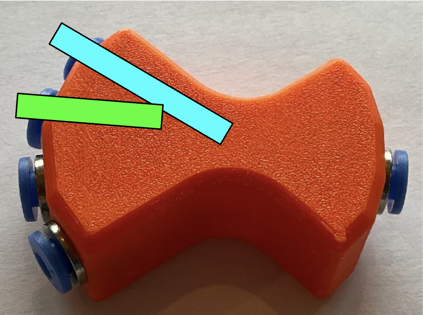
Next, attach PTFE to the end of the 3MS extruder and to another input on the Y-splitter. Load the filament manually through the 3MS extruder until it wedges itself against the loose filament. In the above diagram, the green filament represents the filament in the 3MS extruder.
In the Mainsail/Fluidd console, run:
If the stepper skips steps, your run_current is properly set.
If the stepper grinds the filament, your run_current is too high. Reduce it by 0.05-0.1, restart Klipper, and repeat this test until the stepper skips steps.
Warning
Make sure when reducing stepper current that it also passes the free filament test as well as the blocked filament test.
Mitwirken
Beitragen
Wenn du zum 3MS-Projekt beitragen möchtest, befolge die folgenden Anweisungen.
Development Setup
Folge dem Development Setup, um dein System für die Entwicklung mit 3MS einzurichten.
Pull Request
Reiche abschließend eine pull request ein. Ein Entwickler wird sich bald mit dir in Verbindung setzen und dir Feedback geben, bevor deine Pull Request in das Hauptprojekt integriert wird.
Vielen Dank für deinen Beitrag zum 3MS-Projekt!
Development Setup
Folge dieser Anleitung, um dein System für die Entwicklung mit dem 3MS einzurichten.
Veränderungen der Dokumentation
- Erstelle eine Fork des 3MS Repositories
- Erstelle einen neuen Branch für deine Anfrage (aus dem
docsBranch)1. Install Python. - Installiere Pipenv.
- Navigiere in deinem Terminal zum Ordner 3MS und führe aus:
- Entwickle die Änderungen im neuen Branch und benutze den folgenden Befehl, um die Dokumentation lokal auszuführen: