Zum Inhalt

BTT SKR Pico

Max filament units: 4

MCU Name: mmu

BOM

Name Price Quantity Link Notes
SKR Pico $26.58 1 BIQU
24AWG Power Cables $9.99 1 Amazon These wires are only sufficient to run steppers, not heaters
24V PSU $12.98 1 Amazon This PSU is only sufficient to run steppers, not heaters

For each filament unit, purchase the following:

Name Quantity Price Link Notes
NEMA17 Stepper Motor 1 $9.99 Amazon You can use a pancake stepper if you want, but it will have less torque
BMG Clone Extruder 1 $9.99 Amazon Alternatively, you can use this Dual-drive MK8 based extruder
PTFE Tubing 1 $8.99 Amazon You likely won't need this for every unit, as this is usually too long for only one unit

Wiring

Route the wires from the NEMA17's to the controller board. Follow this table to determine which port to plug the motors into:

Filament Unit # Motor Port
0 X
1 Y
2 Z1 or Z2
3 E

Now, grab your 24V PSU and two M-M duponts, one red and one black (M-M means that there is metal coming out of both ends of the cable). Plug the PSU into the wall, but don't plug the screw terminals into the PSU (the screw terminals have green)

  1. Plug the red wire into the positive terminal of the screw terminals
  2. Plug the black wire into the negative terminal of the screw terminals

    Danger

    These dupont cables are too thin to run much more than the stepper motors. If you run a heater or other power-intensive device off of the SKR board, the duponts and/or PSU can melt/catch fire. To reduce the risk of this, you can double up on the duponts or get thicker wires.

  3. Following this image, locate the POWER input

  4. Route the two wires inside closest to the POWER input
  5. Using the markings on the board, plug the red wire into the positive terminal on the SKR
  6. Using the markings on the board, plug the black wire into the negative terminal on the SKR
  7. Verify all connections

    Warning

    If the wires are plugged into the wrong place, or swapped polarities, your SKR, Stepper motors, and/or PSU can be badly damaged.

  8. Plug the PSU screw terminals into the PSU wire

If the SKR lights up, you wired it correctly!

Finally, plug the SKR into your Klipper host with the blue cable that came with it.

Firmware Installation

Setting up firmware for the SKR Pico can be divided into four major steps:

  1. Compile Katapult (bootloader)
  2. Flash Katapult
  3. Compile Klipper
  4. Flash Klipper

Compiling Katapult

You have two options for installing Katapult to the SKR Pico:

Run the following commands in SSH:

1
2
3
4
cd ~/
git clone https://github.com/Arksine/katapult
cd katapult
make menuconfig

Adjust your menuconfig parameters to match the following exactly.
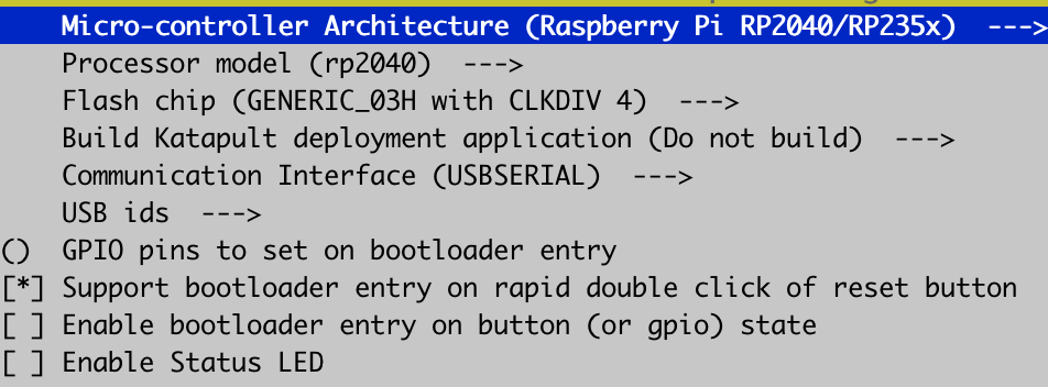
Then, run:

1
2
3
make clean
make
cp out/katapult.uf2 ~/printer_data/config/katapult.uf2

Now in Mainsail/Fluidd, download katapult.uf2 from your printer's config folder onto your computer and proceed to flashing.

Download katapult.uf2 to your computer and proceed to flashing.

Flashing Katapult

Now that you have katapult.uf2 on your computer, install the BOOT and VUSB jumpers onto the SKR Pico as shown in the below diagram.

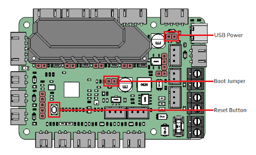
Credits: Voron Design

Plug the SKR Pico into your computer with the USB-C cable that came with it. It should show up as a USB drive.

Drag katapult.uf2 into the drive. It should quickly disconnect then reconnect itself.

Now, remove the BOOT jumper and unplug the Pico from your computer.

Compiling Klipper

Now, SSH into your Pi again and run the following commands:

cd ~/klipper
make menuconfig

Adjust your menuconfig settings to match this exactly:
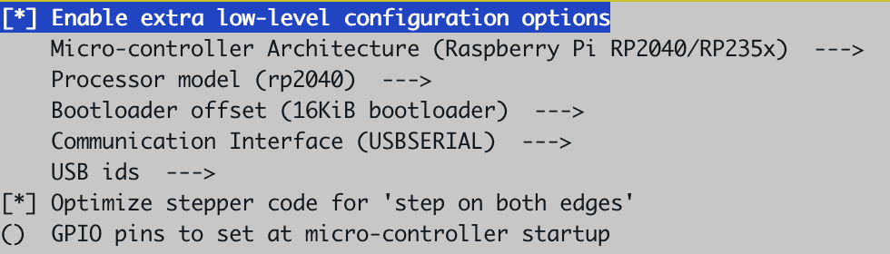
Now, run:

make clean
make

Flashing Klipper

Run in SSH:

ls /dev/serial/by-id/*

Plug the Pico into your Pi.

ls /dev/serial/by-id/*

There should be a new USB device shown after plugging the Pico in. Copy the entire path, including /dev/serial/by-id/, and run the final commands:

cd ~/klipper
make flash FLASH_DEVICE=<PASTE HERE>

Your SKR Pico is now successfully flashed with Katapult and Klipper.

Kommentare